12
10.4 ADJUSTING INTERNAL JUMPERS
Several ALiX settings can be adjusted via internal
jumpers. While it’s not trivial to do, if you are handy with
a screwdriver and tweezers, you’ll be ne. This is not
something you should attempt to do on a dark stage or in
the back of the tour van. Directions for disassembling the
chassis and accessing the jumpers is as follows:
IMPORTANT: Before you do anything, disconnect ALiX
from the AC power, disconnect all cables and place ALiX
on a at stable surface with good lighting.
1. DOUBLE CHECK: Did you completely disconnect the
power supply? Ok then.
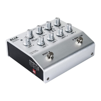
2. With a #2 phillips screwdriver, remove the 4 chassis screws,
located on the outer edges of the front bottom and rear
bottom of the aluminum top chassis (gure 1) .
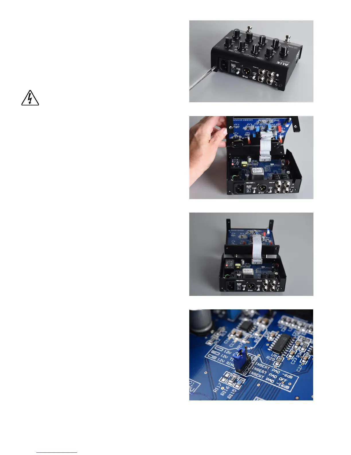
3. Orient the unit so the rearpanel is facing forward towards
you. Carefully pull up on the top chassis and ip it up
and over the bottom chassis (gure 2). This will reveal the
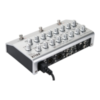
top and bottom circuit boards. Do not pull them apart
any further than the ribbon cables that connect them
will allow. The top should rest easily on the work surface
ipped over and behind the bottom chassis (gure 3).
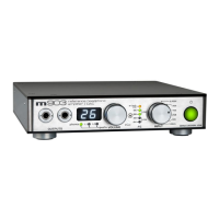
4. Now refer to the jumper location diagram on the following
page to move any jumpers you wish (closeup - gure 4).
5. To move a jumper, use tweezers or your ngernails to
gently pull the jumper o of its header pins. To reposition
the jumper, double check the diagram, then gently press
the jumper back down in the correct location.
6. J10 resides on a 2-pin header. If you wish to set this to
a non-jumpered setting, simply push one side of the
jumper down onto one pin, so that the two pins are not
connected.
7. When you are nished adjusting the jumpers, make sure
there are no loose jumpers or any other junk lying around
inside your ALiX.
8. Then carefully reassemble the top and bottom chassis,
making sure to let the ribbon cable fold easily back in
place. If there is any tension or something isn’t tting
properly, carefully pull the top and bottom back apart and
inspect for interference.
9. Once you have put the unit back together, replace the 4
screws, making sure they go in straight and true. You may
need to nudge the top panel back and forth a bit to ensure
the holes in the top panel chassis line up evenly with the
inner threaded holes.
10. Do not tighten the screws until all 4 are cleanly started in
the threads. Take your time and remember, cross-threading
is a crime.
gure 1
gure 2
gure 3
gure 4