EasyManua.ls Logo

Graco 190ES 309063F User Manual

Graco 190ES 309063F
28 pages
To Next Page IconTo Next Page
Page #1 background imageLoading...
Page #1 background image
309063F
First choice when
quality counts.t
REPAIR
Important Safety Instructions
Read all warnings and instructions in this
manual. Save these instructions.
- For portable spray applications of architectural paints and coatings -
190ESt
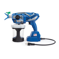
Airless Paint Sprayers
3000 psi (207 bar, 20.7 MPa ) Maximum Working Pressure
120 VAC
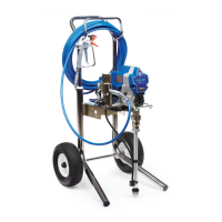
232900, A, B, C, D, E, F
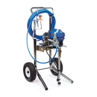
232901, A, B, C, D, E
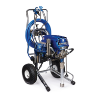
233797, A, B, C, D, E
233815, A, B, C, D, E
100--120 VAC
232903, A, B
220--240 VAC
232906, A, B
Table of Contents
Component Function and Identification 5............
Pressure Relief Procedure 6.......................
General Repair Information 7......................
Grounding 8.....................................
T roubleshooting 9................................
Spin Test 12.....................................
Motor Brush Replacement 12.....................
On/Off Switch Replacement 14....................
Pressure Control Repair 19.......................
Drive Housing Replacement 24....................
Motor Replacement 25............................
Displacement Pump Replacement 26...............
Technical Data 27................................
Graco Phone Number 28..........................
Graco Warranty 28...............................
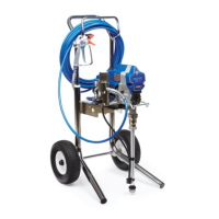
232900
309064.....................
309045.......
309060.......
309065.......
309365.......
ti7400a

Questions and Answers:

Graco 190ES 309063F Specifications

General IconGeneral
Max Pressure3000 PSI
Weight26 lbs
Model190ES 309063F
Hose Length50 ft
Power SourceElectric
Voltage120V
Spray PatternAdjustable
Horsepower0.625 HP
TypeAirless
Amperage7.5 A
Tip Size0.015 in
MotorDC Motor

Summary

Important Safety Instructions

General Safety Guidelines

General safety guidelines and warnings to be read before operating the equipment.

Specifications

Equipment Specifications Overview

Details on equipment specifications and usage limitations.

Warnings and Safety Symbols

Warning and Caution Symbols Explained

Explanation of warning and caution symbols used in the manual.

Fire and Explosion Hazard

Details risks and precautions related to flammable fumes and ignition sources.

Electric Shock Hazard

Addresses dangers of electric shock due to improper grounding or usage.

Skin Injection Hazard

Warns about high-pressure fluid injection injuries and necessary precautions.

Equipment Misuse Hazard

Highlights risks associated with incorrect equipment operation or modification.

Pressurized Aluminum Parts Hazard

Warns against using specific solvents with aluminum parts, causing rupture.

Burn Hazard

Advises caution regarding hot equipment surfaces to prevent burns.

Toxic Fluid Hazard

Details risks of toxic fluids or fumes and proper handling procedures.

Personal Protective Equipment

Specifies necessary protective gear for safe operation and servicing.

Moving Parts Hazard

Warns about the dangers of moving parts and the need for guards.

Component Identification and Function

Sprayer Component Identification

Details and identifies the various components of the sprayer system.

Pressure Relief Procedure

Safe Pressure Relief Steps

Step-by-step instructions for safely relieving pressure in the sprayer.

General Repair Information

Repair Guidelines and Precautions

Provides essential guidelines and precautions for performing sprayer repairs.

Grounding and Electric Requirements

Grounding and Electrical Safety

Details essential grounding procedures and electrical requirements for safe operation.

Troubleshooting

Common Sprayer Problem Resolution

Guides users through identifying and resolving common sprayer problems.

Spin Test

Motor Armature and Wiring Test

Procedure for testing motor armature and wiring for shorts or open circuits.

Motor Brush Replacement

Motor Brush Replacement Procedure

Detailed steps for removing and replacing worn motor brushes.

On/Off Switch Replacement

120 Vac Procedure

Removal and installation steps for the on/off switch on 120 Vac units.

Wiring Diagrams for 120 Vac Models

Illustrates various wiring configurations for 120 Vac sprayers.

100 Vac Procedure and Wiring

Steps for switch replacement and wiring diagram for 100 Vac units.

240 Vac Procedure and Wiring

Steps for switch replacement and wiring diagram for 240 Vac units.

Pressure Control Repair

Motor Control Board Diagnostics

Troubleshooting the motor control board using LED indicators.

Motor Control Board Replacement

Detailed steps for removing and installing the motor control board.

Pressure Adjust Potentiometer

Procedure for removing and installing the pressure adjust potentiometer.

Pressure Control Transducer

Procedure for removing and installing the pressure control transducer.

Motor Control Board (Specific Models)

Instructions for motor control board replacement on specific sprayer models.

Pressure Control Removal and Installation

Steps for removing and installing the pressure control unit.

Drive Housing Replacement

Drive Housing Disassembly and Assembly

Instructions for disassembling and assembling the drive housing.

Motor Replacement

Motor Removal and Installation

Detailed procedure for removing and installing the sprayer motor.

Displacement Pump Replacement

Pump Replacement Procedure

Steps for removing and installing the displacement pump and its components.

Technical Data

Sprayer Technical Specifications

Provides key technical specifications and dimensions of the sprayer.

Graco Information

Contact and Ordering Information

Contact information for ordering parts, service, and additional resources.

Related product manuals