Repair
Reassembly
NOTE: Lubrica
te all o-rings when reassembling.
Plug Seals Repair Kit 420011 is available. Parts
includedinthekitaremarkedwithanasterisk,for
example (12*). Order the kit separately.
Lever Seals Repair Kit 420012 is available. Parts
included in the kit are marked with a symbol, for
example (2◆). Order the kit separately.
Outlet Seal
s Repair Kit 420013 is available. Parts
included in
thekitaremarkedwithasymbol,for
example (8†
). Order the kit separately.
Ball Repair Kit 24T752 is available. Parts included in
the kit are marked with a symbol, for example (6‡).
Order the kit separately.
1. Install the backup washers (3◆) and o-ring (2◆)
on the valve stem (4). Insert the stem into the
body (1).
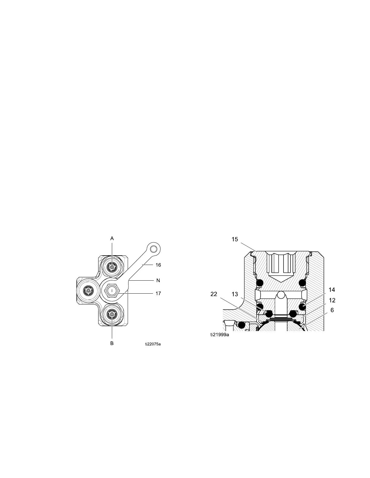
2. Screw the packing nut (5) into the body (1) so it
bottoms on the shoulder. Install the lever (16)
and nut (17) so the notch (N) in the lever faces
the B side, as shown.
Figu
re 5 Lever Orientation
3. Mov
e the lever to the SPRAY position. Install the
ste
m ball (6) in the manifold body (1) so the small
hol
e on one side of the stem is facing the side
of t
he body marked SPRAY (A). The ball must
eng
age with the valve stem (4).
4. In
stall the bearing (8†) and o-ring (9†). Insert
th
e mix nozzle (10) into the stem ball (6) so it
bottoms on the shoulder. Loosely screw the
outlet fitting (11) into the body (1).
5. Apply thread adhesive to the check valves
(19, 20). Be sure to install the A and B check
valves (19) in the correct ports, as noted under
Disassembly.
6. Check that the lever (16) is in the SPRAY
position. This positions the ball stem (6) so the
smooth rounded surface is facing the solvent
port. Proper positioning is important to ensure
that the seal (22) conforms properly against the
ball.
7. Apply a small amount of fluid compatible grease
to the seat (12) and seal (22). Install them in the
solvent plug port, with the beveled side of the
seat (12) facing in, toward the ball (6).
8. Install the o-rings (13*, 14*) on the solvent plug
(15) and screw the plug into the solvent port
securely.
9. Move the lever (16) to the FLUSH position. This
positions the ball stem (6) so the smooth rounded
surface is facing the A and B ports. Repeat steps
7and8fortheAandBplugs.
Figu
re 6 Detail of Seal and Seat Assembly
10. When
all three plugs (15) are installed, tighten
the
outlet fitting (11).
11. Rec
onnect the hoses, A to A and B to B.
Rec
onnect the solvent hose.
12. Ret
urn the mix manifold to service.
3A2801A
7