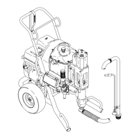
ELECTRIC MOTOR REPLACEMENT
Fig
12
75
26
46
44
16
66
47
74
34
65
82
17
9
4
55
63
5
NOTE:
Refer to Fig 12 for this procedure.
If the electric motor (63) won’t run and the circuit, on/off
switch and fuse are good, relieve pressure, unplug the
sprayer
and proceed as follows.
1. Remove the shield (1 19), the four screws (9) and
washers (17) and the upper fan guard (82). Loosen
the
fan blade setscrew and remove the fan (26).
2. Remove the switch box cover (34) and disconnect
the power cord wires. Do not to scratch the smooth
mating surfaces of the switch box (65) and cover
(34).
3. Drive out the two spring pins (16) and then pull out
the handle (75). Hook the switch box conduit with a
hoist
and lift the unit about 6 in. (150 mm) of
f the floor
.
Pull the cart frame (74) down out of the support
mounting
(44) and move it out of the way
.
4.
Remove the eight screws (4) and washers (5) hold
-
ing the reservoir mounting (44). Raise the unit high
enough
for the
reservoir (66) to clear
. Pull the reser
-
voir
down of
f the unit and
pour out the hydraulic fluid.
5. Carefully
lower the unit and tilt it back until the arms
of
the support mounting (44) are resting on the floor
.
6. Put the cart handle (75) through the arms. Hold the
hook
on the switch box (65) as you lower the unit to
make
sure it doesn’t slip of
f.
7. Remove the four electric motor mounting screws (7
–
see page 20), hold the motor
(63) by the shaft and
switch
box (65), and then rock it from side to side to
free
it from the support mounting. Carefully pull it out
of
the cooling coils (46).
8. Screw
the switch box (65) and
nipple (1
1 – see page
20)
out of the motor
. T
ake the coupling off the motor
shaft
and install it on the new
motor
. When installing
the nipple and switch box, engage the threads at
least
five full turns.
9. Carefully slide the new motor through the cooling
coils (46), forcing it into the support mounting, and
tightly
install the mounting screws.
10. Set the gap between the two coupling halves at
0.31 in. (0.8 mm), and then tighten the coupling
setscrew
securely. See Fig 13, page 19.
11. Clean
the reservoir (66) of sediment and reassemble
the unit using a new gasket (47). Fill the hydraulic
fluid
reservoir through the fill hole filter (55).
 Loading...