HYDRAULIC PUMP REPAIR
Electric
motor wiring diagram
See Fig 13.
Model
226–433 and 231–004 are
wired for 1
15 volt ser
-
vice. It can be rewired for 230 volt service. Model
226–432 is wired for 220 volt service. Check your local
code
before rewiring it for 1
10 volt service, which draws
22 amps.
Fig 13
9
10
4
3
5
BROWN
BLUE
GREEN
GREEN
GREEN
BLACK
WHITE
BLACK
WHITE
9
104
35
3
9
105
4
FOR
1
15V SERVICE
(Models 226–433 and 231–004 only)
FOR 230V SERVICE
(Models 226–433 and 231–004 only)
FOR 220V SERVICE
(Model 226–432 only)
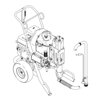
Replacing the hydraulic pump
1. Unplug the sprayer. Relieve pressure. Remove the
shield (119). Disassemble the sprayer as in ELEC-
TRIC MOT
OR REPLACEMENT
, page 18.
2.
Loosen the setscrew in the coupling half (19). Push
the coupling against the hydraulic pump (64). See
Fig
12. Remove the four screws (1), the washers (5)
(see page 20) and the hydraulic pump. Discard the
o–ring
seals. See Fig 14,15 and page 20.
3. Remove the adjusting sprocket retaining nut (29)
and pull the sprocket of f the adjusting nut. See Fig
14.
4. Apply light grease to the o–rings. Place the o–rings
on the pump mounting. Put the coupling half on the
shaft
of the new pump and leave it loose. See Fig
14.
5. Carefully put the pump in place on the mounting so
you
don’t disturb the o–ring seals. Install the mount
-
ing
screws tightly
. Push the coupling half into the oth
-
er
coupling half until there is a 0.31 in. (0.8 mm) clear
-
ance between them, and then tighten the coupling
setscrew
firmly
. See Fig 14.
6. Put
the adjusting chain onto the
sprocket, then onto
the adjusting nut, and then screw the retaining nut
(29)
onto the stud and tighten until snug. Finally
,
back
off
the nut 1/12 to 1/8 turn. See Fig 14.
7. Clean the reservoir of sediment. Reassemble the
sprayer.
Pour hydraulic fluid into the reservoir
. Check
the
fluid level and add fluid as necessary
.
Fig 14
1/32”
(0.8 mm)
GAP
63
46
20
19
7
29
64
45
TIGHTEN SNUGLY AND THEN
BACK OFF 1/12 T
O 1/8 TURN
44
Fig
15
19
64
O–RING
102–620
O–RING
104–130
 Loading...