Motor
WARNING
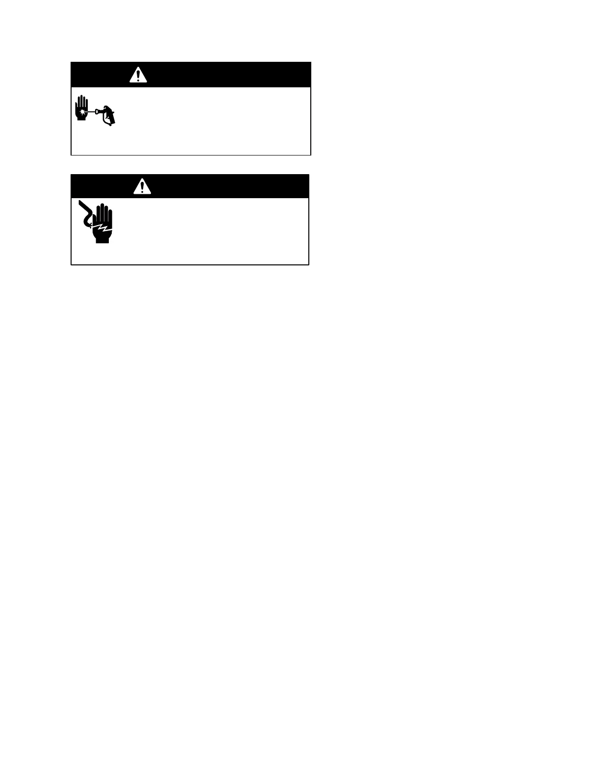
INJECTION
HAZARD
T
o reduce the risk of serious injury
,
whenever you are instructed to relieve
pressure, follow the
Pressure Relief
Procedure
on page 8.
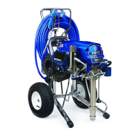
WARNING
ELECTRIC SHOCK HAZARD
T
o reduce the risk of Electric Shock: wait
5 minutes after turning sprayer of
f before
servicing to allow stored current to dis
-
charge.
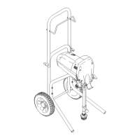
NOTE:
Refer to Fig 13 and parts list except where
noted.
1.
Relieve pressure.
2.
Remove motor shield (14) and front cover (31).
Disconnect hose (132).
3.
Remove outlet cover on pressure control wiring
box. Disconnect four motor leads. See Fig. 14.
4.
Unscrew conduit fitting (125) from motor and pull
four motor leads from conduit (22).
5.
Remove screws (51) from drive housing. Remove
screws (21 and 30) from motor (1).
6. T
ap rear of pump (39) with plastic mallet to loosen
drive housing (18) from motor (1). Pull of
f drive
housing.
NOTE:
Do not drop the gear cluster (9), which may
stay engaged in the motor bell or in the drive housing.
Do not lose the thrust balls (10) or drop them between
the gears. The balls usually stay in the shaft recesses,
but they can be dislodged. If the balls are not in place,
the bearings will wear prematurely
.
7. Lower pressure control (130) by unscrewing motor
mounting
screws (37).
8.
Lift of
f motor (1).
9.
Mount and center new motor on frame and attach
pressure control (130) with motor mounting
screws (37).
10.
Insert motor leads through conduit fitting (125) and
conduit (22) to pressure control. Screw connector
(125) two or three threads into motor
. Tighten
locknut up to motor. Connect four motor leads.
See Fig. 14.
11.
Liberally grease gear cluster (9) and pinion gear
(G). Pack all bearings in motor bell. Be sure thrust
balls (10) are in place.
12.
Place bronze–colored washer (18b) and then
silver–colored washer (18a) on shaft protruding
from big gear in drive housing (18).
13.
Align gears and push drive housing (18) straight
onto motor bell (F) and locating pins.
14.
Continue to reassemble sprayer
.