308-490 5
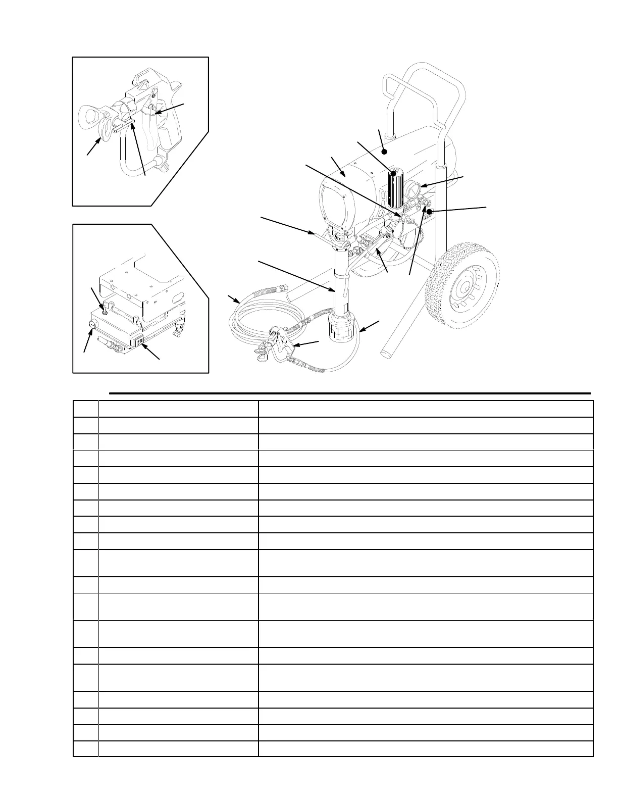
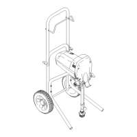
Major
Components
04426A
7148A
C
Fig.
1
J
E
F
A
G
K
R
04463
N
B
H
S
U
L
T
P
V
M
vv
D
A
Motor (Under shield shown)
DC motor
, 220 V
ac, 50 Hz, 12A, 1 phase
B
Pressure Adjusting Knob
Controls fluid outlet pressure
C
ON/OFF Switch
Power switch that controls 220 V
ac power to sprayer
D
Drive Assembly
T
ransfers power from DC motor to the displacement pump
E
Fluid Filter
Filter of fluid between source and spray gun
F
Secondary Fluid Outlet
Second hose and spray gun is connected here
G
Pail Hanger
Container of fluid to be sprayed may be hung here
H
Displacement Pump
Pressures fluid to be sprayed through spray gun
J
15 m (50 ft) Main Hose
3/8 in. ID, grounded, nylon hose with spring guards on both ends
K
RAC IV T
ip Guard
Reverse-A-Clean (RAC) tip guard reduces the risk of fluid injection inju
-
ry
L T
exture Spray Gun
21.0 MPa (210 bar
, 3000 psi) texture spray gun with gun safety latch
M
RAC IV Switch T
ip
RAC switch tip atomizes fluid and removes clogs from spray tip without
removing tip from spray gun
N
0.9 m (3 ft) Hose
1//4 in. ID, grounded, nylon hose used between 50 ft hose and spray
gun to allow more flexibility when spraying
P
Pressure Drain V
alve
Relieves fluid pressure when open
R
Pressure Control
Controls motor speed to maintain fluid pressure. W
orks with pressure
adjusting knob.
S
Spray Gun Safety Latch
Inhibits accidental triggering of spray gun
T
Primary Fluid Outlet Hose and spray gun is connected here
U
10/12 Amp Switch
Allows sprayer to operate on 10A service with reduced performance
V Gauge
System pressure indicator
, 21.0 MPa (210 bar
, 3000 psi)