Bearing
Housing and Connecting Rod
WARNING
INJECTION
HAZARD
T
o reduce the risk of serious injury
,
whenever you are instructed to relieve
pressure, follow the
Pressure Relief
Procedure
on page 8.
NOTE:
Stop the sprayer at the bottom of its stroke to
get the crank (H) in its lowest position.T
o lower the
crank manually
, rotate the blades of the motor fan with
a screwdriver
.
1.
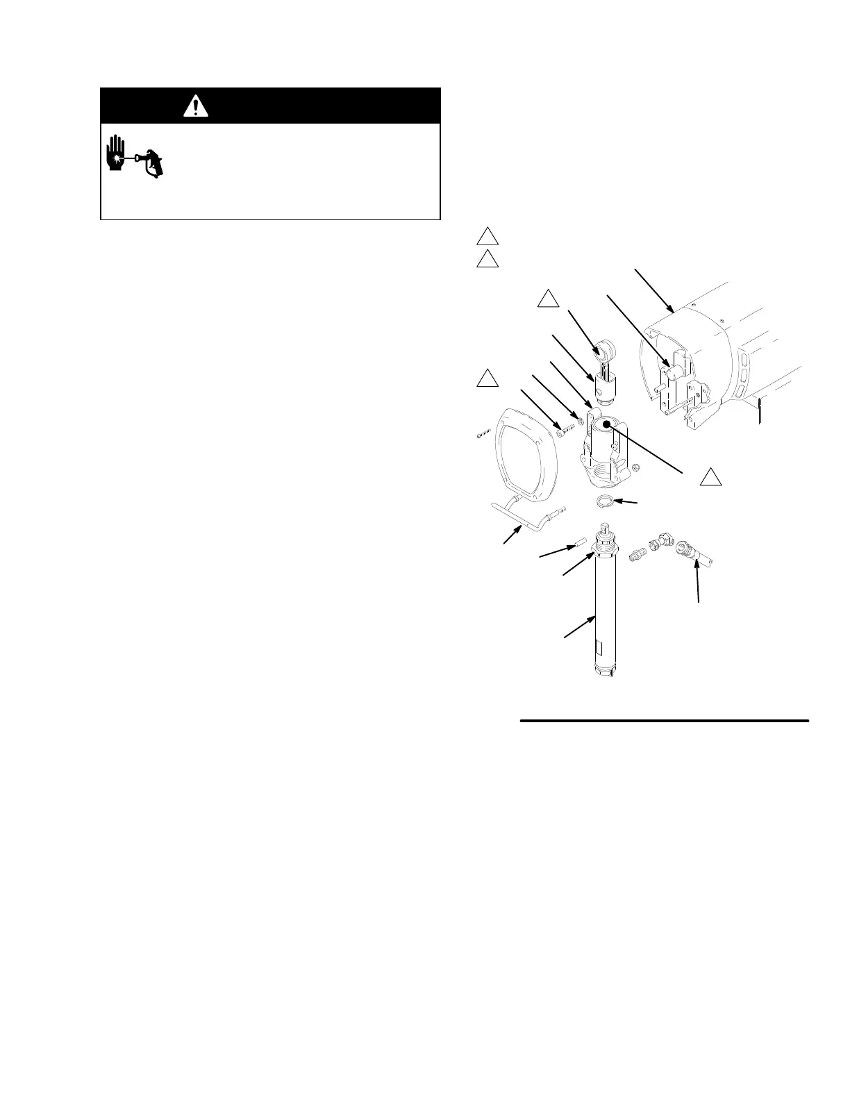
Remove pump. See page 16.
2.
Remove front cover (31). Remove bearing housing
screws (33). See Fig. 18 and part list.
3. T
ap lower rear of bearing housing (27) with plastic
mallet to loosen it from drive housing (18). Pull
bearing housing and connecting rod (29) straight
of
f drive housing.
4.
Inspect crank (H) for excessive wear and replace
parts as needed.
5.
Evenly lubricate inside of bronze bearing (K) with
motor oil. Liberally pack roller bearing (J) with
bearing grease.
6.
Assemble connecting rod (29) and bearing housing
(27).
7.
Clean mating surfaces of bearing and drive hous
-
ings.
8.
Align connecting rod with crank (H) and align
locating pins in drive housing with holes in bearing
housing (27). Push bearing housing onto drive
housing or tap into place with plastic mallet.
9.
Install bearing housing screws (33). T
orque evenly
to 34 N.m (300 in–lb).
10.
Reinstall all parts. See page 16 to install pump.
04351A
Fig 18
1
2
49
27
29
J
H
18
K
33
132
20
35
38
39
1
31
Torque
to 34 n.m (300 in-lb)
Lubricate
2
2