308-490 21
Pressure
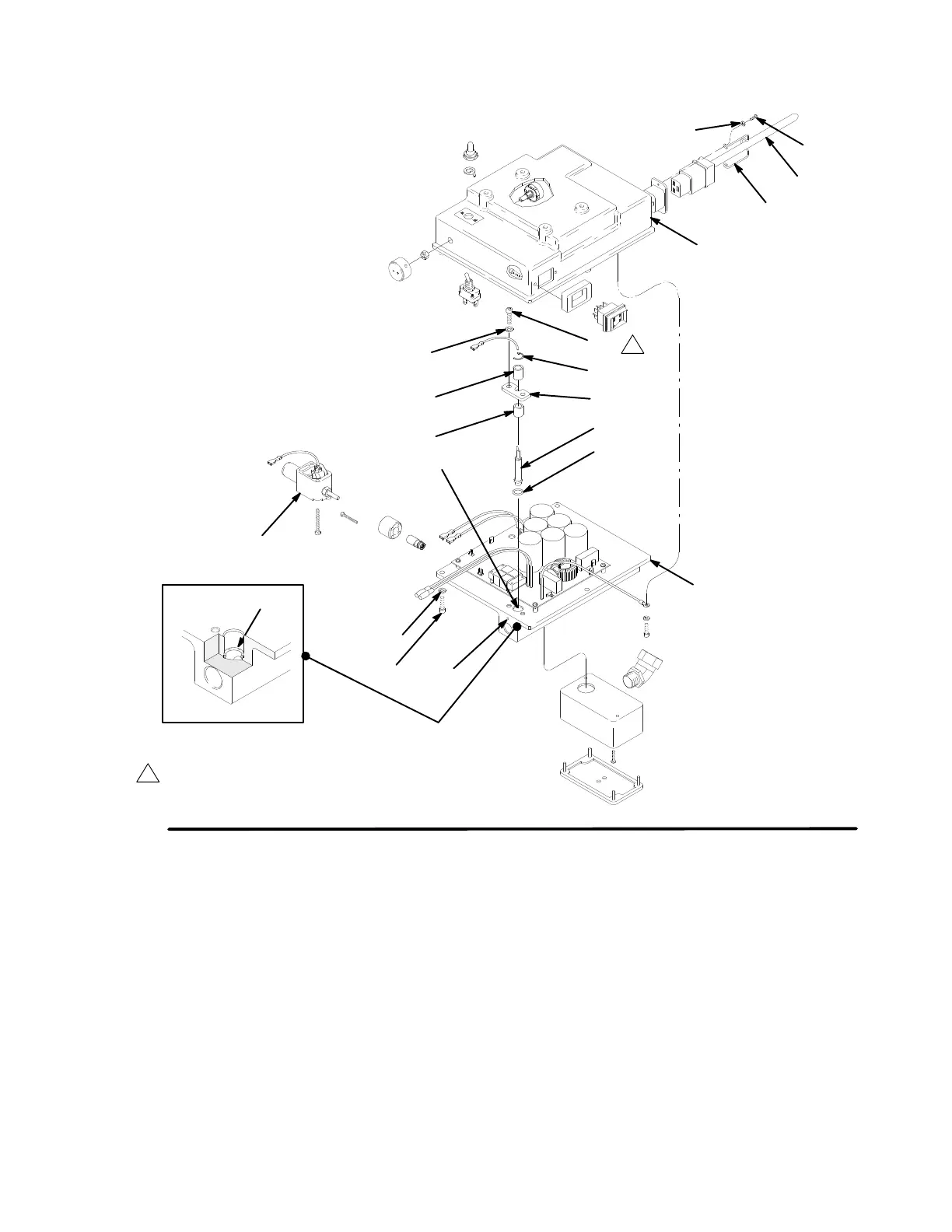
Control Repair
7135B
Fig
16
214
202
213
201
23
230
23a
229
227
C
A
219
220
215
214
213
216
217
218
1
Torque
to 17 N–m (150 in. lbs)
1
B
2. Carefully
slide new o–ring (220) down bore (A) of
motor control (201) into o–ring groove (B). Make
sure o–ring is in groove around its entire circumfer
-
ence.
NOTE:
O–ring (220) is made of which is more
dif
ficult to work with.
3.
Carefully slide new transducer and plastic
spacer (217) down bore. Loosely attach
bracket (218), screws (213), and washers (214).
4.
Seat transducer into o–ring by drawing down
screws and washers until bracket is flush with
motor control surface.
5.
Carefully remove transducer and verify that o–ring
is seated correctly and not pushed out of groove. If
not seated correctly use new o–ring and repeat
steps 2 through 5.
6.
When o–ring is correctly installed, reinstall trans
-
ducer and tighten screws to 17 N–m (150 in. lbs).
Install spacer (216) and C–clip (215). Re–connect
electrical lead and re–assemble sprayer
.
7.
Follow Airless Operation start–up procedures for
sprayer on page 7 using compatible fluid.
8.
Inspect weep hole (C) for any leakage.
9.
If any leakage is present, replace o–ring repeating
steps 1 through 9.
 Loading...