Fluid Supply
312775J 21
10. Install the two setscrews and o-rings (L3*). Install
the long setscrew (S) at the front of the housing, for
ease of access.
11. Screw the static mixer (SM) into the injection cap
(M*). Install the retained fitting (F) on the static
mixer tube and secure with the nut (N1).
12. Follow instructions under Fluid Connections on
page 18.
NOTE: Use a minimum 20 ft (6.1 m) x 1/4 in. (6 mm) ID
gun fluid supply hose when using dynamic dosing. If the
material is harder to integrate, use a longer hose.
13. Tune the fluid pressure and flow as explained in the
ProMix 2KS Operation Manual.
NOTE: When using dynamic dosing it is very important
to maintain a constant, well-regulated fluid supply. To
obtain proper pressure control and minimize pump pul-
sation, install a fluid regulator on the A and B supply
lines upstream of the meters. In systems with color
change, install the regulator downstream of the
color/catalyst valve stack.
F
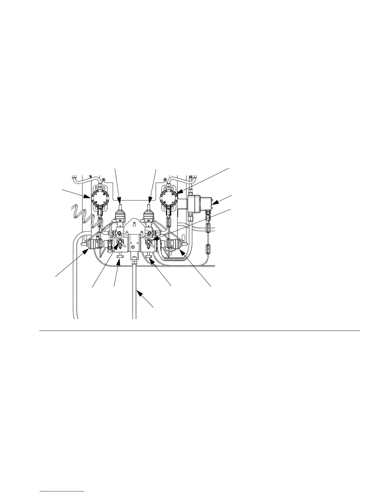
IG. 10. Wall Mount Fluid Station, Dynamic Dosing
TI13874b
MA
MB
DVB
MS
SPV
DVA
APV
SM
SVA SVB
RVB
RVA
Key:
MA Component A Meter
DVA Component A Dose Valve
RVA Component A Sampling Valve
SVA Component A Shutoff Valve
MB Component B Meter
DVB Component B Dose Valve
RVB Component B Sampling Valve
SVB Component B Shutoff Valve
MS Solvent Meter (accessory)
SPV Solvent Purge Valve
APV Air Purge Valve
SM Static Mixer

 Loading...