Component Identification
12 311075R
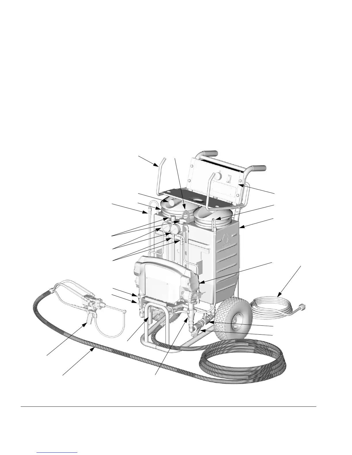
Key for FIG. 2
A Supply Tank A
B Supply Tank B
C Pump A
D Pump B
G Fluid Pressure Gauges
H Recirc/Spray and Overpressure Relief Valves
J Control Panel; see F
IG. 3, page 13
K Electric Motor and Drive Housings
L Hose Bundle
M 2K Ultra-Lite Spray Gun, with disposable static
mixer
N Desiccant Dryer (mounts on supply tank A)
P Recirculation Tubes
Q Air Line Inlet (quick-disconnect fitting)
R Outlet Hose Connections
U Hose Rack and Control Shield
V Fluid Inlet Ball Valves (1 on each side)
W Fluid Inlet Strainers (1 on each side)
XPower Cord
Y Lift Ring
Z Air Filter/Moisture Separator
FIG. 2: Component Identification, Nonheated Packages (Part No. 249808 Shown)
TI6989b
A
N
B
C
D
G
H
J
K
L
M
P
P
R
U
V
W
X
Y
Q
Z