Repair
44 311075R
8. Reassemble in reverse order. Mount tem-
perature display so Heater Power switch off
(0) position is at left when facing control
panel.
Replace Function
Knob/Potentiometer
2. Remove access cover (39) from back of
control module.
3. Disconnect potentiometer wires from J2 on
control board (406). See FIG. 12.
4. See F
IG. 11. Remove two setscrews (416a)
and pull function knob (416) off potentiome-
ter (404) shaft.
5. Remove nut (N, part of 404) and detent
plate (415).
6. Install new potentiometer (404) in reverse
order. Position potentiometer so slot (S) is
horizontal. Position knob (416) so pointer
(P) faces up. Install knob on shaft so slot
(S) engages alignment pin in knob. Push
knob onto shaft against detent spring
before tightening setscrews (416a).
7. Reconnect potentiometer wires to J2 as
shown in F
IG. 12.
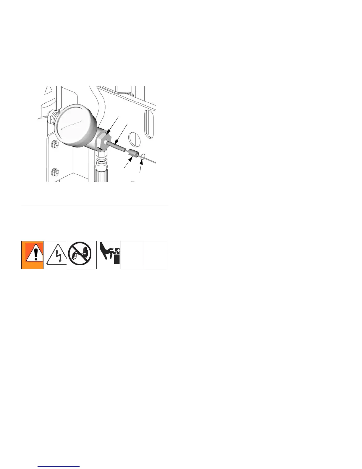
FIG. 10. Temperature Sensor
1. See Before Beginning Repair, page 39.
Relieve pressure, page 27.
TI7067b
66g
424
66d
66e