EasyManua.ls Logo

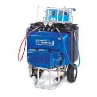
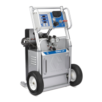
Graco REACTOR E-XP1

Graco REACTOR E-XP1
44 pages
To Next Page IconTo Next Page
Loading...
Reactor Error Code Trouble Shooting Guide
Rev 2.6 (02/2014) Page 1

Other manuals for Graco REACTOR E-XP1

Questions and Answers:

Graco REACTOR E-XP1 Specifications

General IconGeneral
Max Pressure3300 PSI
Weight35 lbs
Power SourceElectric
Hose Length50 ft
Maximum fluid working pressure3300 PSI
Voltage120V
ApplicationsInterior/Exterior Painting
Max Flow Rate0.42 GPM
Maximum output0.42 GPM
Tip Size Range0.015-0.021 inches

Summary

Troubleshooting Guide Introduction

Safety Warnings - Electrical & Chemical

Electric Shock, Toxic Hazards, and PPE

Covers electric shock, toxic fluids/fumes, and personal protective equipment.

Skin Injection Hazard

Warns about high-pressure fluid piercing skin and amputation risk.

Safety Warnings - Operational Hazards

Fire, Thermal, Misuse, and Burn Risks

Details fire, thermal expansion, equipment misuse, and burn hazards.

E01: High Fluid Temperature

Thermocouple Connection and Continuity Checks

Verify electrical connections and resistance of 'A'/'B' thermocouples.

E01: Thermocouple and Switch Checks

Over-Temperature Switch and Thermocouple Seating

Test switch continuity and verify thermocouple seating in heater.

E02: High Current

Heater Module Short Circuit Diagnosis

Troubleshoot electrical shorts within the heater module.

E02: Hose Heat Transformer Issues

Hose Heat Transformer Short Check

Diagnose shorts in the hose heat transformer for the hose zone.

E03: No Zone Current

Circuit Breaker and Connection Checks

Verify circuit breakers and check for loose or broken connections.

E04: Thermocouple Communication Issues

Checking A and B Thermocouple Assemblies

Verify electrical connections and continuity of 'A' and 'B' thermocouples.

E04: Hose Heat FTS Communication

Checking Hose Heat FTS Connections

Verify electrical connections and continuity of the hose heat FTS.

E05: Control Module Over Temperature

Module Over-Temperature Cause

Heat is turned off if module temperature exceeds 185°F (85°C).

E06: Communication Cable Issues

Loose or Faulty Communication Cable

Check cable connections for continuity; replace if faulty.

E09: Display Communication Malfunction

Wiring and Connection Checks

Check all wiring between display and heater control module.

E21: No Component A Transducer

Transducer and Connection Checks

Diagnose faulty transducer or connection on the motor control board.

E22: No Component B Transducer

Transducer and Connection Checks

Diagnose faulty transducer or connection on the motor control board.

E23: High Pressure Troubleshooting

Jumper and Pressure Switch Checks

Verify jumper connections and test pressure switches for failure.

E23: Transducer Signal Issues

High Pressure Transducer Signal Diagnosis

Check transducer signals above 3000/4500 psi and test with known good transducer.

E24: Pressure Imbalance

Analog Gauge Readings Analysis

Analyze equal or unequal analog gauge readings for imbalance causes.

E24: Transducer Failure Testing

Testing Pressure Transducer Functionality

Use dip switches to test pressure transducer functionality.

E25 E26: Line Voltage Issues

High and Low Line Voltage Checks

Verify supply voltage is within correct range for the motor control board.

E27: High Motor Temperature

Causes and Cooling Fan Checks

Reduce pressure, check cooling fan, airflow, and cover placement.

E28: High Motor Current (E-Series)

Motor Control Board vs. Motor Issues

Differentiate issues between motor control board and motor drive system.

E29: Brush Wear (E-Series)

Brush Sensor and Wiring Checks

Inspect brush sensor, spade plug, and wiring for false alarms.

E30: Momentary Loss of Communication

Wiring and Connection Checks

Check wiring between display and control board for loose connections.

E31: Motor Drive Error (E-Series)

Motor Board and Drive System Checks

Diagnose motor board failure or motor drive system issues.

E31: Reversing SwitchCycle Rate (H-Series)

Flow Rate and Switch Checks

Check flow rate, reversing switch, and connections on J5.

E32: Motor Control Heat Sink Over Temperature

Heat Sink Temperature Monitoring

Monitors control board temperature to prevent damage.

E99: Loss of Communication

Display and Control Board Wiring

Check wiring between display and control boards for communication loss.

Recommended Start-up Technician Tool Set

Essential Measurement Tools

Lists clamp meter and pocket thermometer for diagnostics.

Mechanics and Pliers Tool Sets

Includes mechanics tool set, pliers set, and punch set for repairs.

Additional Recommended Tools

Specialty Tooling

Lists punches, wrenches, strippers, and hammers for maintenance.

Related product manuals