15309251
On/Off Switch Replacement
695/795/1095 240 Vac (245004, 245005, 245009)
Removal
1.
Relieve pressure; page 4.
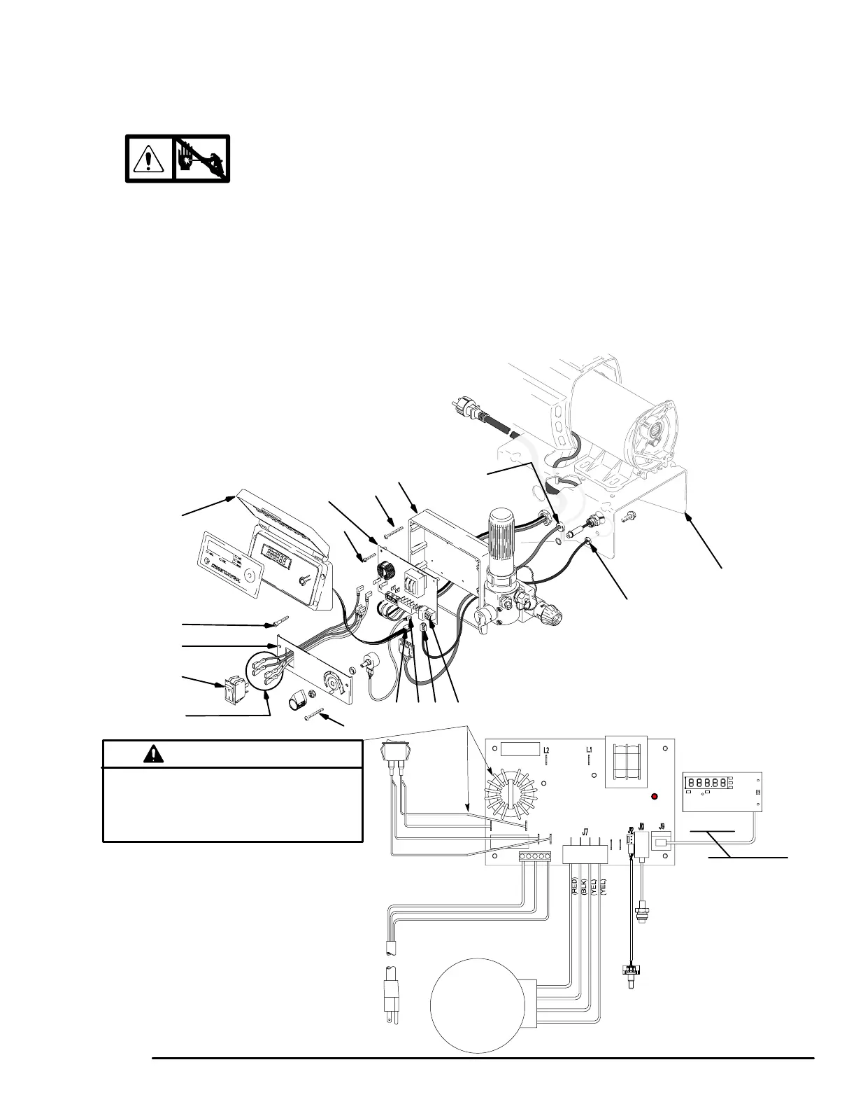
2. Fig. 12. Remove four screws (60) and pressure
control cover (49). Disconnect display connector (B).
3. Remove two screws (108) and control panel (67).
4. Disconnect four wires (A) at ON/OFF switch (86).
5. Squeeze inside tabs on ON/OFF switch (86) and
remove from control panel (67).
Installation
1. Push ON/OFF switch (86) into control panel (67)
until inside tabs snap in place.
2. Connect four wires (A) to ON/OFF switch.
3. Install control panel (67) with two screws (108).
4.
Install display connector (B). Install pressure control
cover (49) with four screws (60).
Display
Not available
on all sprayers
LED
Wiring Diagram
Heat from inductor coil of filter board may destroy
wire insulation that comes in contact with it. Ex-
posed wires could cause shorts and component
damage. Bundle and tie all loose wires so none lay
in contact with inductor coil of filter board.
CAUTION
Pressure
Transducer
Ref 68
Potentiometer
Ref 64
Power
Cord
Ref 66
On/Off
Switch
Ref 86
Motor
Blue
ti0897A
Red (+)
Black (–)
Yellow
Brown
Blue
Brown
Fig. 12
695/795/1095 240 VAC
42
72
108
49
60
86
A
67
112
41
D EBC
43
108
58

 Loading...