16 309251
Pressure Control Repair
Motor Control Board
Removal
Refer to Fig. 10, 11 or 12 depending on sprayer and
voltage.
1.
Relieve pressure; page 4.
2. Remove four screws (60) and pressure control
cover (49). Disconnect display connector (B).
3. Remove two screws (108) and control panel (67).
4. Disconnect at motor control board (112):
Motor connector: two yellow, black (+) and
red (–).
Lead (D) from potentiometer.
Lead (E) from transducer.
Wires from power cord and switch
5. Remove six screws (41) and motor control
board (112).
Installation
1. Clean pad on rear of motor control board. Apply
small amount of thermal compound 073019 to pad.
2. Fig. 10. Install motor control board (112) with six
screws (41).
3. Connect to motor control board (112):
Lead (E) to transducer.
Lead (D) to potentiometer.
Motor connector: two yellow, black (+) and
red (–).
Wires to power cord and switch
4. Route loose wires so none lay in contact with
inductor coil on filter board (not 120 Vac sprayers).
See Wiring Diagram CAUTION, Fig. 11.
5. Install control panel (67) with two screws (108).
6. Install display connector (B). Install pressure
control cover (49) with four screws (60).
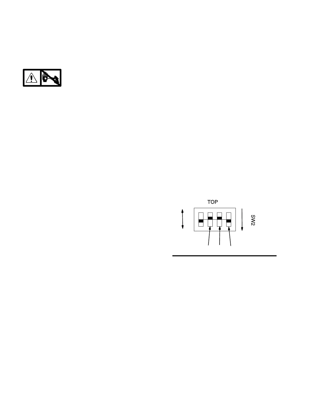
Digital Display Settings (Not available on
all sprayers)
The units on the digital display may be set to psi, bar,
MPa and gallons or liters.
1. Fig. 10. Remove four screws (60) and cover (49).
Disconnect display cable (B).
2. Set switches as desired, Fig. 13.
Fig. 13
MPa bar
liters
gallons
psi
SET
Shown set for
gallons and psi

 Loading...