Installation and Setup
18
Installation and Setup
NOTE:
See , page 27, to aid in component installation.
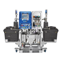
Connect Air Lines
Refer to component identification in FIG. 1, page 9.
Refer to the pneumatic schematic drawings in the XM
Plural-Component Sprayer repair-parts manual 313289
for guidance.
• Connect air lines (68, 69) between the fluid control
assembly (B) and the control box (C).
• Connect air lines (68, 69) between the air controls
assembly (E) and the control box.
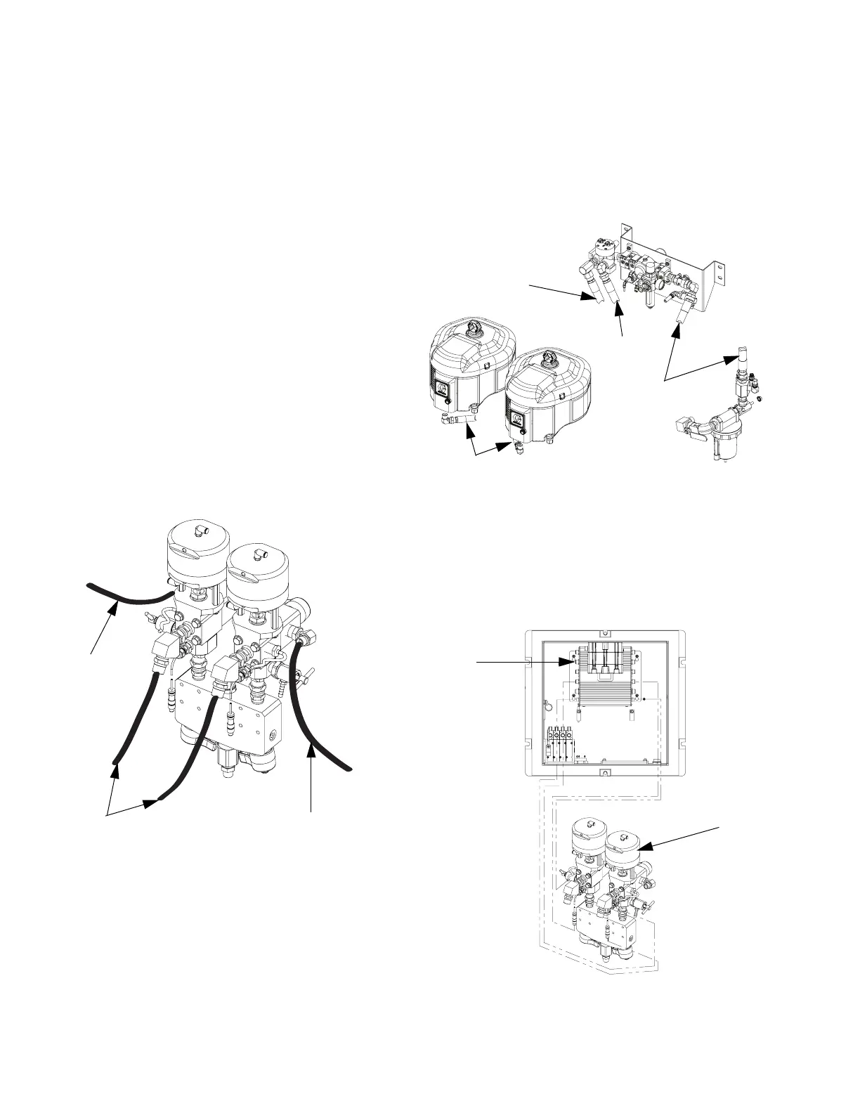
Connect Fluid Hoses
Use the following illustration as a guide to connect the
fluid hoses.
Connect Air Hoses
• Connect air hose (12) between air inlet manifold and
air controls assembly. (Hose called out as 12(C)).
• Connect air hose (12) between air controls assem-
bly and both air motors. (Hose called out has 12(A)
and 12 (B)).
Connect Sensor Cables
Connect pressure and temperature sensor cables (sup-
plied with fluid control assembly (B)) to the fluid control
module.
Recirculation
Hose (gray)
Hose to Pump
Lower (black)
Recirculation
Hose (gray)
12 (A and B)
12(C)
12(B)
12(A)
r_xmaa00_313292_4a
B
Fluid
Control
Module