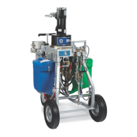
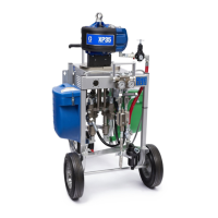
System Components
20 3A0420ZAF
System Components
* Indicates a customer-supplied component required to
add to Bare Pump Packages (part numbers ending in
zero “0”) to make a complete system.
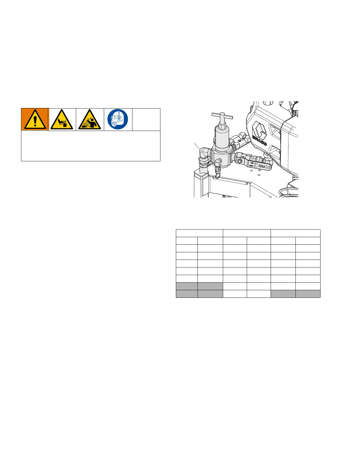
*Bleed Type Motor Air Valve (MA)
Be sure the valve is easily accessible from the pump
and located downstream from the air regulator (MB).
The two steps below are required in your system to
relieve air trapped between the air motor when the valve
is closed:
1. Open the valve to supply air to the motor.
2. Close the valve to shut off air to the motor, and
bleed any trapped air from the motor.
*Air Pressure Relief Valve (MG)
Automatically opens to relieve air pressure if supplied
pressure exceeds preset limit. Use the correct air
pressure relief valve for the system ratio:
See Models (page 10) for Maximum Regulated Air
Pressure to ensure proper air pressure relief valve
installed.
Trapped air can cause the pump to cycle
unexpectedly, which could result in serious injury
from splashing or moving parts. Use the Bleed Type
Master Air Valve to relieve trapped air.
XP35 XP50 XP70
Ratio Valve Ratio Valve Ratio Valve
1:1 114055 1:1 113498 1:1 114055
2:1 16M190 1.5:1 103347 1.5:1 116643
2.5:1 113498 2:1 113498 2:1 114055
3:1 114055 2.5:1 114055 2.5:1 113498
4:1 103347 3:1 113498 3:1 113498
3.3:1 103347 4:1 113498
4:1 113498
 Loading...