GRT7-TH4E
Rev. 01 de 15/01/2014
2.4 - DIAGRAMA DE BLOCOS/BLOCK DIAGRAM/DIAGRAMA DE BLOQUES
www.grameyer.com.br 11 / 27
F
F
IGURA
IGURA
F
F
IGURA
IGURA
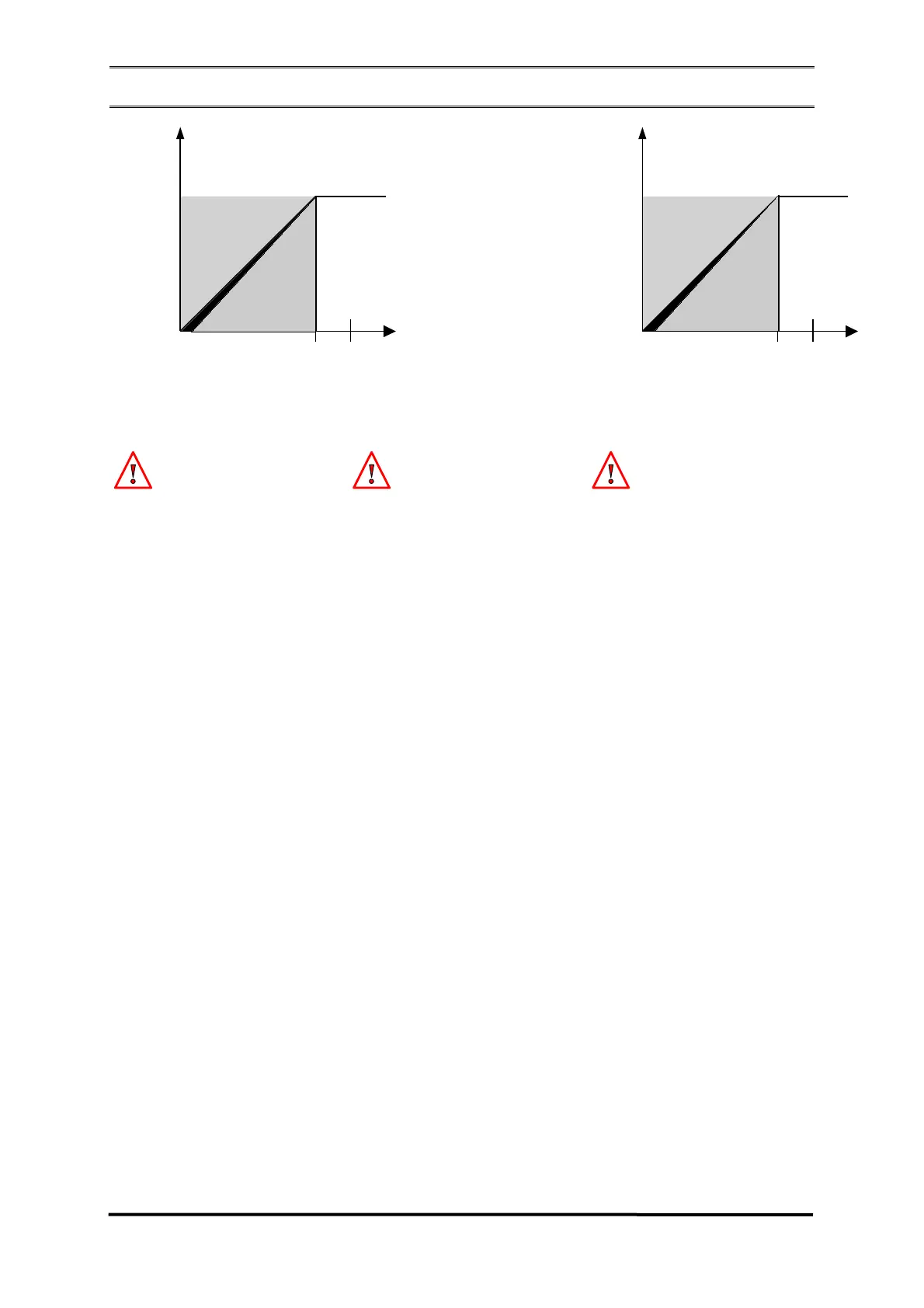
2.3.2
2.3.2
- P
- P
ONTO
ONTO
DE
DE
ATUAÇÃO
ATUAÇÃO
DA
DA
PROTEÇÃO
PROTEÇÃO
U/F
U/F
/
/
U/F P
U/F P
ROTECTION
ROTECTION
A
A
CTUATION
CTUATION
P
P
OINT
OINT
/
/
P
P
UNTO
UNTO
DE
DE
ACTUACIÓN
ACTUACIÓN
DE
DE
LA
LA
PROTECCIÓN
PROTECCIÓN
U/F
U/F
Tensão de Saída (Vca)
Output Voltage(Vac)
Tension de salida(Vca)
Frequência
(Hz)
Un
45 50
U/F
Tensão de Saída (Vca)
Output Voltage (Vac)
Tensión de salida(Vca)
Frequência
(Hz)
Un
54 60
U/F
Atenção
Não deixar a proteção U/F abaixo de
20% da frequência nominal. A
configuração deve ser feita conforme
Figura 2.3.2 para evitar problemas no
desligamento.
A frequência limitada pelo U/F é a
frequência da forma de onda que se
encontra na entrada de alimentação do
circuito e não da entrada de
realimentação (tensão de saída do
gerador).
Attention
Do not leave the U/F protection below
20% of the rated frequency. The
configuration must be as per Figure
2.3.2 to prevent shut-off problems.
The frequency limited by the U/F is the
waveform frequency which is found at
the power supply input and not at the
sensing input (generator output
voltage).
Atención
No deje la protección U/F abajo de 20%
de la frecuencia nominal. La
configuración debe ser realizada
conforme la Figura 2.3.2 para evitar
problemas en la desconexión.
La frecuencia limitada por el U/F es la
frecuencia de la forma de onda que se
encuentra en la entrada de alimentación
del circuito y no de la entrada de
realimentación (tensión de salida del
generador)
O funcionamento é baseado na
comparação do valor eficaz da tensão de
realimentação com a referência de
tensão, ajustada pela soma do trimpot
P1 com o trimpot externo. O erro é
processado pela malha de realimentação
cujo valor determina o ângulo de disparo
do tiristor que pode variar de 0 a 180°,
controlando desta forma a tensão de
saída do gerador. Com zero grau de
disparo tem-se zero volts na saída do
retificador, e com disparo de 180 graus,
tem-se a saída máxima dada pelo
retificador de meia onda.
The operation is based on the
comparison of the effective value of
sensing voltage with the reference
voltage, adjusted by the sum of trimpot
P1 with the external trimpot. The error
is processed by the sensing mesh whose
value determines the thyristor trip angle
which may vary from 0 to 180°,
controlling thus the generator output
voltage. With 0° of triggering we have
zero volts at the rectifier output, and
with trigger of 180° we have the
maximum output given by the half wave
rectifier.
El funcionamiento está basado en la
comparación del valor eficaz de la
tensión de realimentación con la
referencia de tensión, ajustada por la
suma del trimpot P1 con el trimpot
externo. El error es procesado por la red
de realimentación, cuyo valor determina
el ángulo de disparo del tiristor que
puede variar de 0 hasta 180°,
controlando, de esta forma, la tensión
de salida del generador. Con cero
grados de disparo se tiene cero voltios
en la salida del rectificador y con el
disparo de 180 grados se tiene la salida
máxima dada por el rectificador de
media onda.