GRT7-TH4E
Rev. 01 de 15/01/2014
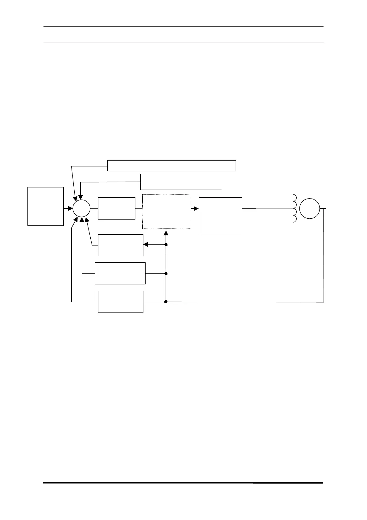
A estrutura do regulador é apresentada na Figura 2.4.1.
The regulator structure is presented in Figure 2.4.1.
La estructura del regulador es presentada en la Figura 2.4.1.
www.grameyer.com.br 12 / 27
F
F
IGURA
IGURA
2.4.1
2.4.1
-
-
D
D
IAGRAMA
IAGRAMA
DE
DE
BLOCOS
BLOCOS
/
/
B
B
LOCK
LOCK
D
D
IAGRAM
IAGRAM
/
/
D
D
IAGRAMA
IAGRAMA
DE
DE
BLOQUES
BLOQUES
Na Figura 2.4.2, apresenta-se o
diagrama de controle dos reguladores de
tensão GRT7-TH4E . O controle é
baseado no ST1A, apresentado pela
IEEE, aplicado a sistemas onde o
retificador é alimentado a partir da saída
do gerador (
Type ST
–
Static Excitation
Systems
), seja diretamente, por bobinas
auxiliares ou por transformador.
Figure 2.4.2 presents the control diagram
of the voltage regulators GRT7-TH4E .
The control is based on the ST1A,
presented by the IEEE, applied to
systems where the rectifier is supplied
from the generator output (Type ST –
Static Excitation Systems), whether
directly, by auxiliary coils or transformer.
En la Figura 2.4.2, se presenta el
diagrama de control de los reguladores
de tensión GRT7-TH4E . El control está
basado en el ST1A, presentado por la
IEEE, aplicado a sistemas donde el
rectificador es alimentado a partir de la
salida del generador (
Tipo ST
-
Sistema
de Excitación Estática
), sea
directamente, por bobinas auxiliares o
por transformador.
Valor de
Referência/
Reference
Value/
Valor de
Referencia
Campo de
Excitação/
Excitation
Field/
Campo de
Excitacion
Saída do
Gerador/
Generator
Output/
Salida Del
Generador
Entrada Analógica/Analog Input/Entrada Analógica
Entrada Pot. Externa/External
Pot input/Entrada Pot. Externa
PID
U/F
Realimentação
Sensing
Realimentación
DROOP
Escorvamento
Automático/
Automatic Field
Flashing/
Cebado
Automático
Estágio de
Potência/
Potency Stage/
Etapa de
Potencia
G
+
+
+
+
+
-
O início de geração se dá através da
tensão residual do gerador. Após atingir
aproximadamente 10% da nominal, o
regulador controla a tensão do gerador
fazendo com que ela suba através da
rampa inicial em aproximadamente 1
segundo, até atingir o valor nominal. A
partir deste momento, a malha de
controle manterá a tensão de saída do
gerador constante dentro do valor
ajustado.
The generation start takes place through
the generator residual voltage. After
reaching approximately 10% of the
rated voltage, the regulator controls the
generator voltage raising it through the
initial ramp in around 1 second until
reaching the rated value. From such
moment the control mesh will keep
constant the generator output voltage
inside the adjusted value.
El inicio de la generación se da a través
de la tensión residual del generador.
Después de alcanzar aproximadamente
el 10% de la nominal, el regulador
controla la tensión del generador
haciendo con que ella suba a través de
la rampa inicial en aproximadamente 1
segundo, hasta alcanzar el valor
nominal. A partir de este momento, la
red de control mantendrá la tensión de
salida del generador constante dentro
del valor ajustado.