INSTALLATION INSTRUCTIONS Gas Furnace: WFAR
18 440 01 7104 02
Specifications subject to change without notice.
4. Remove the formed grommet from the rubber drain
elbow by cutting the elbow along the vertical line located
about 1--3/8 in. (35 mm) away from the formed grommet.
See Figure 16. DO NOT DISCARD THE FORMED
GROMMET OR THE RUBBER ELBOW. Both of these
pieces will be used.
Assemble and route the drain line to the opposite side of the
furnace as detailed below:
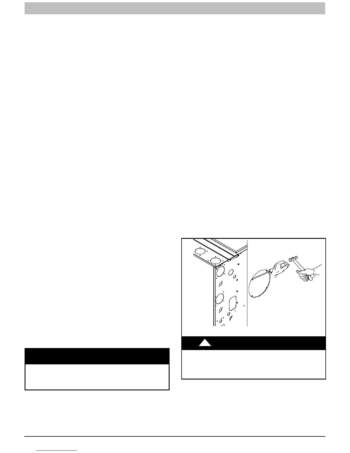
5. Remove the knock--out from the left side of the casing.
(See Figure 12 for suggested knockout removal
technique.)
6. From the outside of the casing, insert the angled end of
the“Z-pipe” through drain hole in the left side of the
casing and behind the inducer or gas valve. Allow
the“Z-pipe” to temporarily rest on the blower shelf
(upflow) or burner box (downflow). (NOTE: When the
inducer housing has been removed to ease installation in
upflow applications, this step is not needed.)
7. After inserting the “Z-pipe” through the casing, slide a
spring clamp over each end of the “Z-pipe”.
8. From inside the casing, insert the short end of the formed
grommet cut from the rubber drain elbow through the
7/8-in. drain knockout in the casing.
9. Pull the grommet through the casing from the outside
until it is seated in the knockout.
10. Align the “Z-pipe” with the long end of the grommet inside
the furnace and insert slightly. The angled end of the
tube at the other side of the casing should be facing the
front of the furnace.
11. Slide a spring clamp over the end of the remaining
rubber drain elbow.
12. Attach the drain elbow to the angled end of “Z-pipe” and
the drain trap outlet stub. Adjust the length of “Z-pipe”
inserted into the grommet at the opposite side of the
furnace as necessary for proper fit and positioning. In
both upflow and downflow orientations, the “Z-pipe”
should NOT be resting on any sheet metal parts.
13. Secure the rubber elbow to the drain trap and the
“Z-pipe” with spring clamps.
14. Secure the grommet to the “Z-pipe” with the spring
clamp. The remaining drain line can be constructed from
field supplied 1/2--in. CPVC or 3/4--in. PVC pipe, in
compliance with local building codes. A factory-supplied
1/2--in. CPVC to 3/4--in. PVC adapter is supplied in the
loose parts bag for use as required.
15. Install the adapter or connect the 1/2--in. CPVC pipe by
sliding a spring clamp over the open end of the grommet
on the outside the furnace casing.
16. Open the spring clamp and insert the long end of the
adapter or the 1/2--in. CPVC pipe into the outlet stub on
the drain elbow.
17. Connect additional condensate piping to a
code-approved drain, or to a condensate pump approved
for use with acidic furnace condensate and compatible
with mineral and vegetable oils, such as canola oil.
Allow at least 1/4-in. per foot (20 mm per meter) of slope down
and away from the furnace in horizontal sections of drain line.
NOTICE
The field-supplied, accessory horizontal drain trap
grommet is ONLY REQUIRED FOR DIRECT VENT
APPLICATIONS. It is NOT required for applications
using single-pipe or ventilated combustion air venting.
TIPS FROM CONTRACTORS: When installing the furnace
horizontally, use the entire drain elbow (that is, do NOT cut as
shown in Figure 16) to connect the trap to the drain line. This
helps to prevent bumps and shocks to the drain line from
damaging the furnace drain trap. Avoid misalignment of the
drain pipe which may cause kinks in the elbow.
Horizontal Orientation
1. The condensate trap outlet extends 2--in. (51 mm) below
the furnace casing. Leave enough clearance between
the furnace and the furnace platform for the trap.
2. To allow for servicing the trap, the condensate drain
elbow in the loose parts bag can be used to make a
coupler to allow for future service of the condensate trap
and drain line.
3. Remove the knock-out for the condensate trap in the
side of the casing.
4. Install the drain trap grommet in the casing if required for
direct vent applications. If necessary, remove the trap,
install the grommet and re-install the trap.
5. Remove the pre-formed rubber drain elbow, and two
spring clamps from the loose parts bag.
6. Connect the full or modified elbow and/or grommet to the
outlet of the condensate trap with one spring clamp.
Avoid misalignment of the drain pipe which may cause
kinks in the elbow or grommet.
7. The remaining drain line can be constructed from
field--supplied 1/2--in. CPVC or 3/4--in. PVC pipe, in
compliance with local building codes. A factory--supplied
1/2--in. CPVC to 3/4--in. PVC adapter is supplied in the
loose parts bag for use as required.
8. Install the adapter or connect the 1/2--in. CPVC pipe by
sliding a spring clamp over the open end of the elbow or
grommet on the outside the furnace casing.
9. Open the spring clamp and insert the long end of the
adapter or the 1/2--in. CPVC pipe into the outlet stub on
the drain elbow.
10. Connect additional condensate piping to a
code--approved drain, or to a condensate pump
approved for use with acidic furnace condensate and
compatible with mineral and vegetable oils, such as
canola oil.
Allow at least 1/4-in. per foot (20 mm per meter) of slope down
and away from the furnace in horizontal sections of drain line.
L12F019
CAUTION
!
CUT HAZARD
Failure to follow this caution may result in personal injury.
Sheetmetalparts may have sharp edgesorburrs.Use careand
wearappropriate protectiveclothing, safety glasses and gloves
when handling parts, and servicing furnaces.
Figure 12 -- Knockout Removal