INSTALLATION INSTRUCTIONS Gas Furnace: WFAR
440 01 7104 02 19
Specifications subject to change without notice.
L14F021
ÄÄÄÄÄÄÄÄÄ
ÄÄÄÄÄÄÄÄÄ
ÄÄÄÄÄÄÄÄÄ
ÄÄÄÄÄÄÄÄÄ
ÄÄÄÄÄÄÄÄÄ
ÄÄÄÄÄÄÄÄÄ
ÄÄÄÄÄÄÄÄÄ
+
+
+
Condensing
Furnace
-
-
-
-
-
Evaporator Coil
+
+
+
< +
< +
< +
+
Blower
-
+ = Positive pressure
< + = Pressure lower than areas with +
ï = Negative pressure
Blower creates positive pressure.
Positive pressure extends into coil
condensate drain (no trap).
Furnace condensate does not flow
consistently when drain is at positive
pressure.
+
DIRECTION
OF
AIRFLOW
+
+
+
+
+
+
+
L14F022
+
+
+
Condensing
Furnace
-
-
-
-
-
ÄÄÄÄÄÄÄÄÄ
ÄÄÄÄÄÄÄÄÄ
ÄÄÄÄÄÄÄÄÄ
ÄÄÄÄÄÄÄÄÄ
ÄÄÄÄÄÄÄÄÄ
ÄÄÄÄÄÄÄÄÄ
ÄÄÄÄÄÄÄÄÄ
Evaporator Coil
+
+
+
< +
< +
< +
+
Blower
-
3/4”
PVC
3/4
1/2”
CPVC
or
larger*
+ = Positive pressure
< + = Pressure lower than areas with +
ï = Negative pressure
+
3/4”
PVC
DIRECTION
OF
AIRFLOW
+
+
+
+
3/4
3/4
3/4
3/4
3/4
+
+
+
+
+
+
+
++
+
+
+
+
Condensing
Furnace
-
-
-
-
-
ÄÄÄÄÄÄÄÄÄ
ÄÄÄÄÄÄÄÄÄ
ÄÄÄÄÄÄÄÄÄ
ÄÄÄÄÄÄÄÄÄ
ÄÄÄÄÄÄÄÄÄ
ÄÄÄÄÄÄÄÄÄ
ÄÄÄÄÄÄÄÄÄ
Evaporator Coil
+
+
+
< +
< +
< +
+
Blower
-
3/4”
PVC
1/2
3/4
1/2”
CPVC
or
larger*
+ = Positive pressure
< + = Pressure lower than areas with +
ï = Negative pressure
+
3/4”
PVC
DIRECTION
OF
AIRFLOW
+
+
+
+
1/2
3/4
3/4
3/4
Open
standpipe
+
+
3/4
+
L14F023
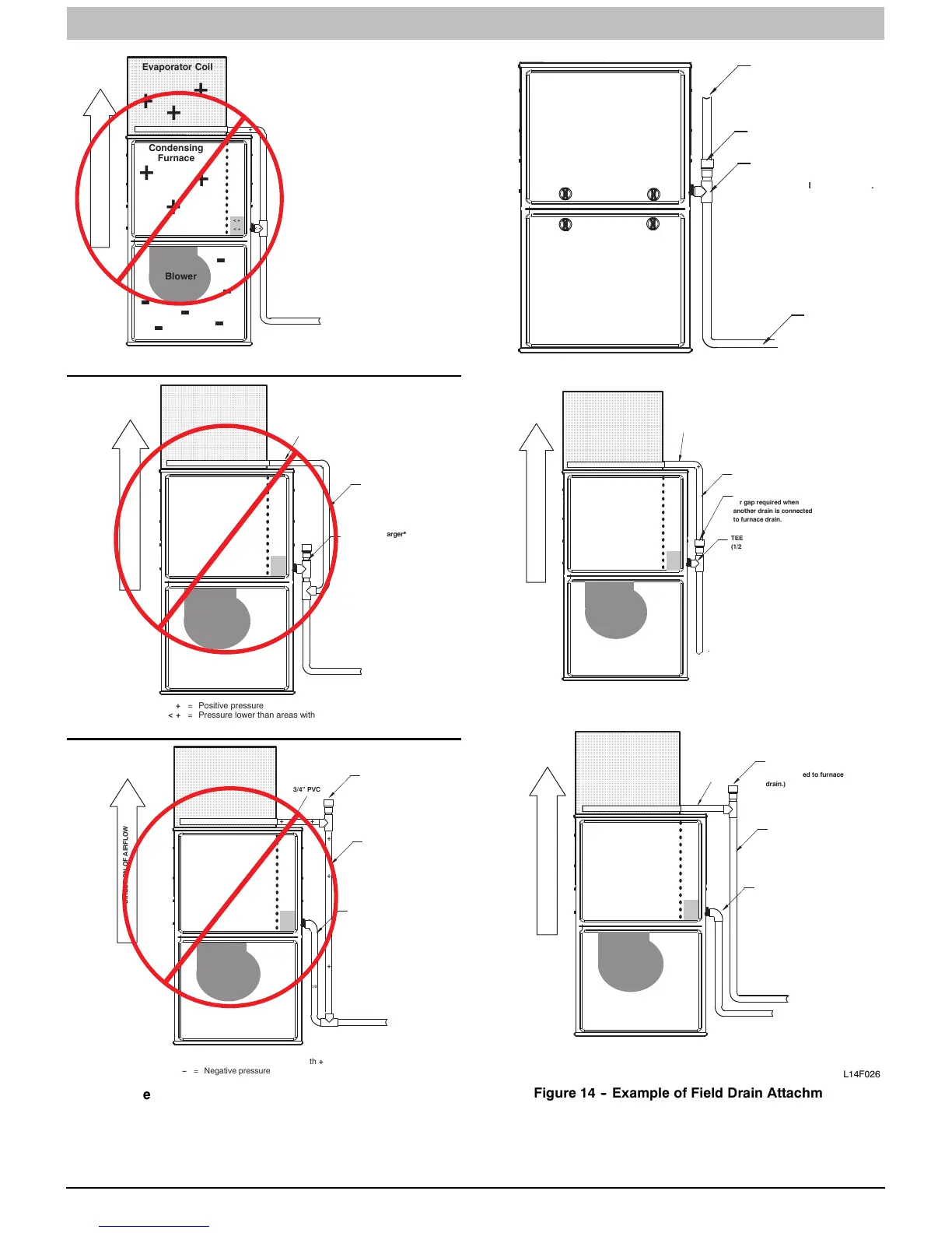
Figure 13 -- Example of Field Drain Attachment
(NOT ALLOWED)
Air
gap
here
Open
standpipe
for
coil
or
humidifier
drain
TEE
(1/2”
CPVC
to
3/4”
PVC
adapter
from
loose
parts
bag.)
To
open
drain
L14F024
L14F025
+
+
+
Condensing
Furnace
-
-
-
-
-
ÄÄÄÄÄÄÄÄÄÄ
ÄÄÄÄÄÄÄÄÄÄ
ÄÄÄÄÄÄÄÄÄÄ
ÄÄÄÄÄÄÄÄÄÄ
ÄÄÄÄÄÄÄÄÄÄ
ÄÄÄÄÄÄÄÄÄÄ
ÄÄÄÄÄÄÄÄÄÄ
Evaporator Coil
+
+
+
< +
< +
< +
+
Blower
-
3/4”
PVC
3/4
3/4
3/4
3/4
+ = Positive pressure
< + = Pressure lower than areas with +
ï = Negative pressure
+
3/4”
PVC
DIRECTION
OF
AIRFLOW
+
+
+
3/4
Open
standpipe
Air
gap
required
when
another
drain
is
connected
to
furnace
drain.
+
TEE
(1/2”
CPVC
to
3/4”
PVC
adapter
from
loose
parts
bag.)
+
+
+
Condensing
Furnace
-
-
-
-
-
ÄÄÄÄÄÄÄÄÄ
ÄÄÄÄÄÄÄÄÄ
ÄÄÄÄÄÄÄÄÄ
ÄÄÄÄÄÄÄÄÄ
ÄÄÄÄÄÄÄÄÄ
ÄÄÄÄÄÄÄÄÄ
ÄÄÄÄÄÄÄÄÄ
Evaporator Coil
+
+
+
< +
< + < +
+
Blower
-
3/4”
PVC
3/4
1/2”
CPVC
or
larger*
+ = Positive pressure
< + = Pressure lower than areas with +
ï = Negative pressure
+
3/4”
PVC
DIRECTION
OF
AIRFLOW
+
+
+
+
3/4
3/4
3/4
3/4
Open
standpipe
(Optional
when
coil
drain
is
not
connected
to
furnace
drain.)
L14F026
Figure 14 -- Example of Field Drain Attachment