INSTALLATION INSTRUCTIONS Gas Furnace: WFAR
52 440 01 7104 02
Specifications subject to change without notice.
NOTES FOR VENTING OPTIONS
1. Attach vent pipe adapter with gasket to furnace casing.
2. Align notches in rubber coupling over standoffs on adapter. Slide clamps over the coupling.
3. Slide vent pipe through adapter and coupling into vent elbow.
4. Insert vent pipe into vent elbow.
5. Torque all clamps 15 lb.--in.
6. Attach combustion air pipe adapter with gasket to furnace.
7. Attach combustion air pipe to adapter with silicone. Pilot drill a1/8--in. hole in adapter and secure with a #7 x 1/2--in. sheet
metal screw.
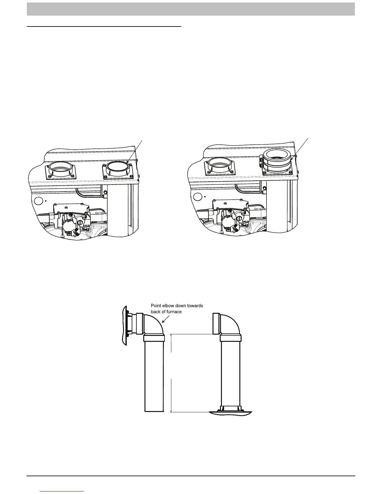
VENT PIPE FLUSH SHOWING COUPLING
VENT PIPE FLUSH WITH ADAPTER
VENT PIPE ADAPTER WITH GASKET
INSTALLED ON FURNACE. VENT
PIPE IS CUT FLUSH WITH TOP OF
ADAPTER. PRIME AND CEMENT VENT
PIPE TO ADAPTER. ALLOW TO DRY
BEFORE INSTALLING VENT COUPLING.
ALIGN NOTCHES IN VENT PIPE
COUPLING OVER STAND-OFF
ON ADAPTER. TORQUE LOWER
CLAMP 15 LB-IN. WHEN REMAINING
VENT PIPE IS INSTALLED, TORQUE
UPPER CLAMP TO 15 LB-IN.
A13076
Figure 49 -- Vent Pipe Flush with Adaptor
A13406
12" (256mm) minimum
to
60”(1524 mm) or
1 additional elbow maximum
CASING SIDE OR TOP ATTACHMENT
COMBUSTION AIR PIPE
(NON-DIRECT VENT FOR ALL MODELS EXCEPT MODULATING UNLESS
INSTALLED IN ATTIC OR CRAWL SPACE)
Figure 50 -- Combustion Air Pipe Attachment