FIRMWARE VERSION 1.0.5.24 GXP2120/GXP2110/GXP2100/GXP14xx USER MANUAL Page 15 of 77
INSTALLATION
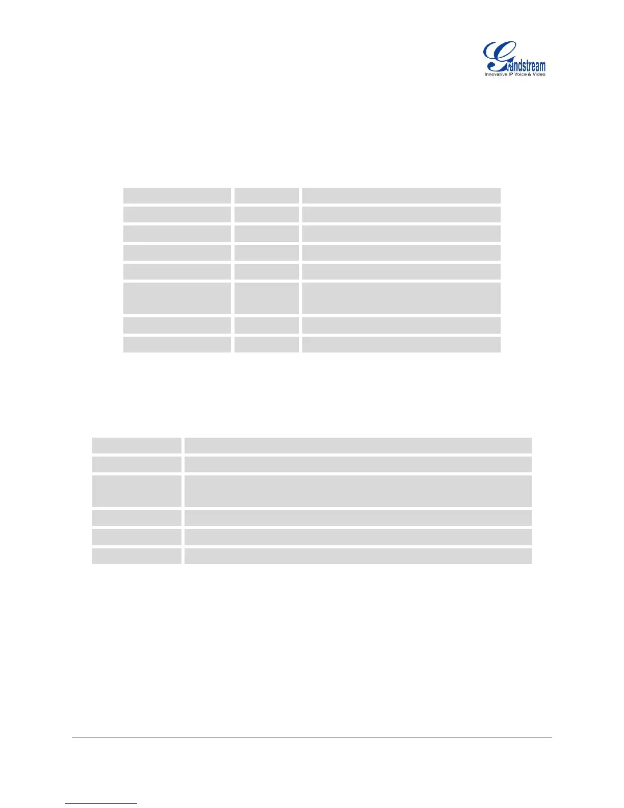
EQUIPMENT PACKAGING
Table 4: GXP2120/GXP2110/GXP2100/GXP14xx EQUIPMENT PACKAGING
2 for GXP2120/GXP2110/GXP2100/1450;
1 for GXP140x
CONNECTING YOUR PHONE
Table 5: GXP2120/GXP2110/GXP2100/GXP14xx CONNECTORS
2.5mm and RJ9 for GXP2120/GXP2110/GXP2100/1450; RJ9 for GXP140x
10/100Mbps RJ-45 port connecting to Ethernet;
Integrated PoE for GXP2120/GXP2110/GXP2100/GXP1450/GXP1405
10/100Mbps RJ-45 port for PC connection
Extension module connection port for GXP2120/GXP2110
5V DC Power connector port
To set up the GXP2120/GXP2110/GXP2100/GXP14xx, follow the steps below:
1. Attach the phone stand or wall mount to the back of the phone where there are slots;
2. Connect the handset and main phone case with the phone cord;
3. Connect the LAN port of the phone to the RJ45 socket of a hub/switch or a router (LAN side of the
router) using the Ethernet cable;
4. Connect the 5V DC output plug to the power jack on the phone; plug the power adapter into an
electrical outlet. If PoE switch is used in step 3 (not applicable to GXP1400), this step could be
skipped;
 Loading...