3.3 FITTING THE BURNER
With all Grant Boiler House models, the burner and boiler are
supplied as standard.
Fit the burner to the boiler as follows:
1. Remove and retain the fi xing nut from the stud on the burner
fl ange on the front of the boiler.
• Leave the small nut in position on the threaded stud.
Check that this nut is fully tightened against the burner
mounting fl ange.
• Do not remove the burner mounting fl ange from the
boiler.
2. Check that the ‘O’ ring around the collar of the burner
combustion head is in position.
3. Fit the burner on the boiler by sliding the combustion head
into the hole in the centre of the mounting fl ange. Locate the
fi xing lug (on the top of the burner) on to the fi xing stud.
4. With the burner level and correctly located into the mounting
fl ange, fi t the nut (previously removed) on to the fi xing stud
and tighten to secure using a 13 mm spanner.
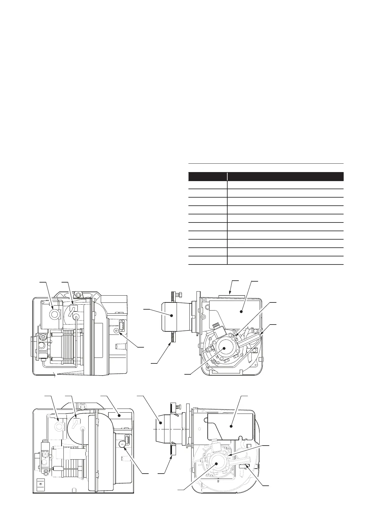
MAIN BURNER COMPONENTS
Table 3-2: Key to Riello RDB burner components
Item Description
1 Reset button with lock-out lamp
2 Photoresistance
3 Snorkel (BF)
4 Blast tube
5 Control box
6 Pump pressure adjustment screw
7 Pressure gauge connection
8 Oil pump
9 Flange with gasket (do not remove from boiler)
10 Air damper adjustment screw
Section 3: Oil Storage and Supply System Page 13
8
9
3
10
5
1
6
7
2
4
Figure 3-6: Riello RDB burner components (15/26, 26/36 and 36/46kW)
8
9
3
10
5
1
6
7
2
4
Figure 3-7: Riello RDB burner components (46/70kW)
3.2.2 TWO PIPE CONNECTION
For either a two pipe (sub gravity) or a single pipe (suction)
system with a deaerator, the following additional items will be
required:
• Flexible fuel hose 3/8 male x ¼ female, 630 mm long (product
code: 20022601)
• 3/8x ¼” BSP adaptor (product code: 3005720)
These are available to purchase from Grant Ireland.
Connect the oil supply to the burner oil pump as follows:
1. Fit the fl exible fuel hose (supplied with the boiler) to the
suction port of the burner oil pump, as detailed in Section
3.2.1.
With either a two pipe (sub gravity) system or a single pipe
(suction) system with a deaerator, the by-pass screw (supplied
with the boiler) must be fi tted to the burner oil pump as follows:
1. Unscrew and remove the blanking plug from the return port
on the burner oil pump and discard it.
2. Fit the by-pass screw into the threaded hole (inside the return
port) and fully screw it in using an allen key.
3. Fit the nut of the elbow connection on the fl exible fuel hose
into the return port and tighten.
4. Fit the ¼ isolating valve (not supplied) to the end of the rigid
oil return pipe (to the deaerator or oil tank) using a fi tting to
suit the pipe size and type (not supplied).
5. Connect the other end of the fl exible fuel hose (not supplied)
to the isolating valve using a x ¼ BSP adaptor (not
supplied).
6. Re-fi t the burner to the boiler. Refer to Section 3.3.