Page 39Section 10: Commissioning
1
2
4mm
+
0
3mm
0
-
5.75mm
0.2
0.5
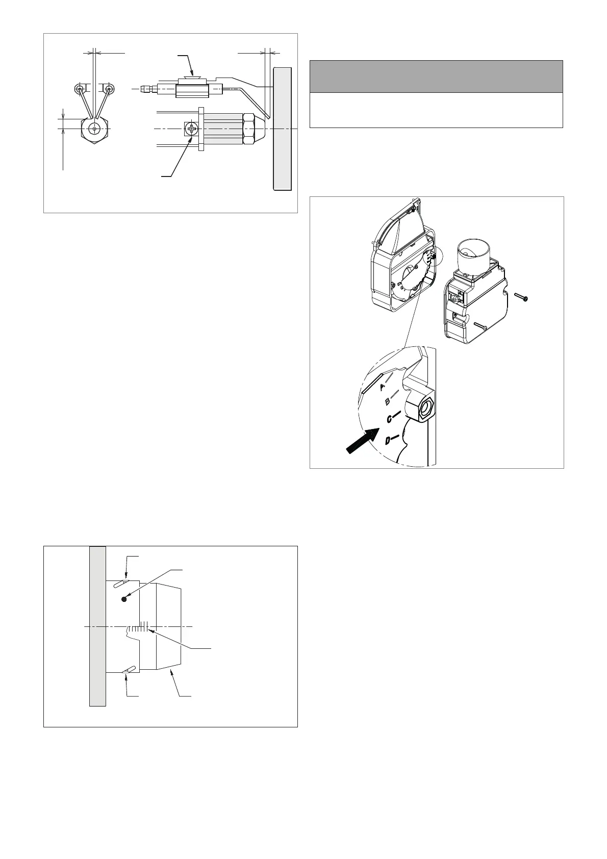
Figure 10-9: Ignition electrode settings
11. Check/adjust the electrode assembly to give the correct gap
(4mm) between the nozzle and electrodes. Refer to Figure
10-9.
• To adjust the electrode position:
- Loosen the electrode clamp screw.
- Slide the electrode assembly to give the correct gap
of 4mm.
- Tighten the electrode clamp screw.
12. Re-fi t the burner head. Refer to Figure 10-8.
• Locate the head fi xing screws in the countersunk slots in
the burner collar.
• Tighten the two screws (3) to secure the head (2) in
position on the burner.
13. Check the combustion head setting.
• The correct head setting depends on the required output
of the boiler. Refer to Table 2-2
• This should be set to ‘0’ in all cases except when the
58/70 is set to maximum (70kw) output.
• In this case the head is set to ‘4’ (i.e. on the 4th line).
Refer to Figure 10-10.
14. To adjust the head setting (if required):
• Loosen the two screws in the curved slots in outer ring
of the head (NOT the two head fi xing screws). Refer to
Figure 10-10.
• Rotate the end of the burner head until either ‘0’ or the
2nd line, as required.
• Tighten the two screws to fi x the head in the required
position.
0
Shutter
Blast tube
Screw
Slotted ring
Screw
Figure 10-10: Riello RDB 3.2 combustion head adjustment
10.4 AIR ADJUSTER DISC:
15/21 AND 21/26 MODELS ONLY
! NOTE !
If the 15/26 model is to be set to 26kW, the air adjuster disc
is not required. It should be removed from the burner and
discarded.
The Riello RDB 2.2 BX burner fi tted to these boilers incorporates
a secondary air adjustment.
This is an air adjuster disc located on the fan housing (inside the
air inlet housing).
It is essential, for correct operation of the burner, that this internal
air adjuster disc is correctly set. Refer to Figure 10-11.
Figure 10-11: Air adjuster disc
To access the air adjuster disc:
1. Ensure the boiler is isolated from the electrical supply.
2. Remove the burner fi xing nut (located at the top of the
mounting fl ange) and withdraw the burner from the boiler.
3. Undo the two screws and remove the air inlet cover from the
side of the burner.
4. The air adjuster disc is mounted on the fan housing. Refer to
Figure 10-11.
5. Check that this disc is correctly set for the factory set output
of the boiler, i.e. with the correct cut-out mark located against
the moulded boss on the fan housing. Refer to Table 2-2 for
correct disc settings. If the disc is not correctly set it MUST
be re-positioned. Refer to step 7 below.
6. If the burner is to be set to a di erent output than the factory
setting, the air adjuster disc MUST be set to the required
setting for that output. Refer to Table 2-2 for correct disc
settings.
7. The air adjuster disc is re-positioned as follows:
• Remove the screw from the centre of the air adjuster
disc.
• Re-position the disc so that the correct cut-out is located
against the moulded boss on the fan housing.
• Replace the screw in the centre of the air shutter disc
and tighten.
8. If the 15/26 model is to be set to 26kW, the air adjuster disc
is not required. It should be removed from the burner and
discarded.
9. Re-fi t the air inlet cover to the side of the burner and secure
in place using the two screws.