Page 18
to the right or to the front of the boiler to avoid clashing with
the fl ue.
A 28mm compression fi tting is provided for making the connection
to the open end of the bent fl ow pipe.
The fl ow pipe from the boiler will need to be vented as it is the
highest point on the primary heat exchanger.
! NOTE !
The pipe to be fi tted into the compression fi tting provided
should be cut using a pipe slicer or pipe cutter, to leave the
end with a slight radius and free from any burrs or sharp
edges. It must NOT be cut using a hacksaw.
RETURN CONNECTION
A 1” BSP socket is provided for the boiler return connection. This
is located on the top of the boiler towards the front on the right
hand side. Refer to Figure 5-2.
The return pipe to the boiler will also need to be vented as it is the
highest point on the secondary heat exchanger.
5.4 46/70 MODELS
FLOW CONNECTION
A 1¼ BSP socket is provided for the boiler fl ow connection. This
is located in the right hand side of the boiler. Refer to Figure 5-4.
The fl ow pipe from the boiler will need to be vented as it is the
highest point on the primary heat exchanger.
Dual stat phials
located in flow
connection at boiler
Figure 5-4: 46/58 and 58/70 models - dual stat, dual stat phials,
fl ow and return connections
RETURN CONNECTION
A second 1¼ BSP socket is provided for the boiler return
connection. This is located on the top of the boiler towards the
front on the right hand side. Refer to Figure 5-4.
The return pipe to the boiler will also need to be vented as it is the
highest point on the secondary heat exchanger.
5.5 FITTING THE DUAL THERMOSTAT
Refer to Section 8 for the dual thermostat electrical connection
details.
The dual thermostat is supplied factory fi tted on the 46/70 and
58/70 Boiler House models. Refer to Figure 5-4.
On all other models the dual thermostat is supplied on a mounting
bracket for fi tting on to the boiler casing by the installer on site. It
is to be located on the top of the boiler, at the front, towards the
right hand side. Refer to Figures 5-1 and 5-2.
To fi t the dual thermostat/mounting bracket:
1. Unscrew and remove the two fi xing screws from the top of
the boiler casing.
2. Position the dual thermostat/mounting bracket such that the
two holes in the fl ange align with the two fi xing holes in the
top of the boiler casing.
3. Secure the dual thermostat/mounting bracket using the two
fi xing screws previously removed.
VORTEX 15/26KW, EUROFLAME 15/26 & 26/36KW
MODELS
To fi t the dual thermostat capillary phials into their pockets on the
boiler:
1. Remove the cover plate located at the top of the boiler right
hand side panel.
To do this, unscrew and remove the two screws from the top
fl ange of the cover plate and remove it from the boiler. Refer
to Figure 5-5.
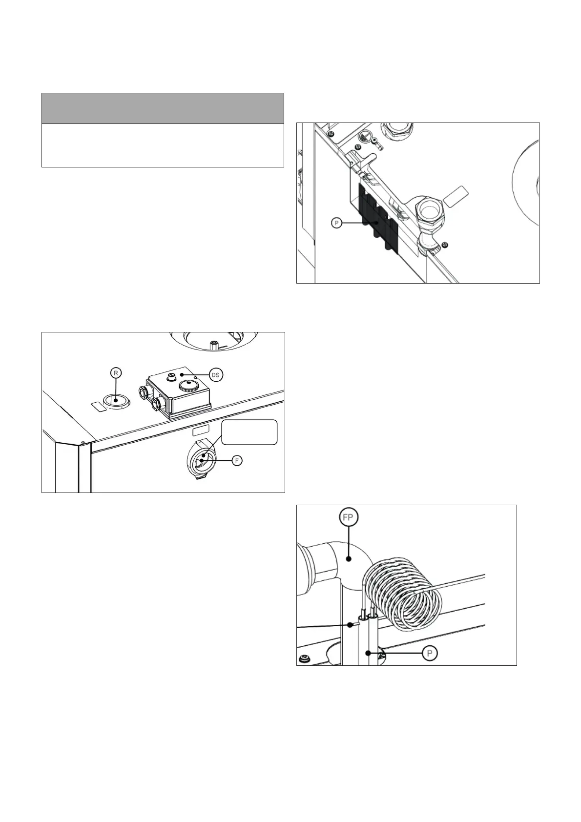
Figure 5-5: Vortex 15/26, Eurofl ame 15/26 & 26/36 model - cover
plate (removed) and dual stat pockets
2. Unwind the thermostat capillaries taking care not to kink or
break them.
3. Locate the two capillary phials in the two pockets on the side
of the boiler, ensuring that the capillaries pass through the
small cut-out in the top casing panel.
4. Refi t the cover plate and secure in position using the two
fi xing screws previously removed.
26/36 & 36/46KW MODELS
On this model the two pockets for the dual thermostat capillary
phials are located on the bent fl ow pipe fi tted into the boiler fl ow
connection. Refer to Section 5.3.
1. Unwind the thermostat capillaries taking care not to kink or
break them.
2. Locate the two capillary phials in the two pockets on the side
of the fl ow pipe.
3. Secure both phials in place by fi tting the split pin provided
through the small holes at the top of the phial pockets. Refer
to Figure 5-6.
Figure 5-6: 26/36 & 36/46kW model - dual stat phials fi tted in
pockets
Section 5: Pipe Connections