Section 3: Oil Storage and Supply SystemPage 12
If a two-pipe system is to be used, the following additional items
will be required:
• Flexible fuel hose 3/8 male x ¼ female, 630 mm long (product
code: 20022601)
• 3/8x ¼” BSP adaptor (product code: 3005720)
These are available to purchase from Grant Ireland.
3.1.5 SINGLE PIPE (SUCTION) SYSTEM WITH
DEAERATOR - (REFER TO FIGURE 3-3)
If the storage tank outlet is below the level of the burner oil pump,
an alternative to the two pipe (sub gravity) system is the single
pipe (suction) system using a deaerator, e.g. a ‘Tiger Loop’
device.
The deaerator creates a loop with the burner oil pump, with the oil
being circulated through the pump out to the deaerator and back
to the pump. Any air in the single pipe lift from the tank is removed
from the oil, collected in the deaerator and then discharged to
outside.
! WARNING !
To prevent any fuel vapour being discharged within
the building, the deaerator must be fi tted outside, in
accordance with BS 5410-1, unless it is specifi cally
designed to be installed inside.
The de-aerator must be mounted vertically at the same level as
(or above) the burner oil pump. Refer to Figure 3-3.
1/4" BSP female
connections
Tiger Loop
SUPPLY
TO PUMP
RETURN
FROM PUMP
SUPPLY
FROM TANK
Figure 3-4: Tiger loop de-aeration device
An external deaerator must not be fi tted within 500 mm of a fl ue
terminal.
Always follow the manufacturers installation instructions supplied
with the deaerator.
To use a de-aertor, the following additional items will be required:
• Flexible fuel hose 3/8 male x ¼ female, 630 mm long (product
code: 20022601)
• 3/8x ¼” BSP adaptor (product code: 3005720)
These are available to purchase from Grant Ireland.
3.2 BURNER OIL CONNECTION
! WARNING !
The blanking plug supplied in the inlet (suction) port is
plastic and will not provide an oil tight seal when the pump
is running.
Ensure that the supply from the tank is connected to this
port and that the plastic plug is discarded.
The burner fuel pump is supplied factory set for use with a single
pipe (gravity) oil supply system.
For ease of access to the burner oil pump connections, the burner
should be removed from the boiler as follows:
1. Remove the red plastic burner cover.
• 15/26, 26/36 & 36/46kW models:
Unscrew and remove the TWO fixing screws from the
red burner cover and remove the cover from the burner.
• 46/70 models:
Unscrew and remove the THREE fixing screws from the
red burner cover and remove the cover from the burner.
2. Unscrew and remove the single burner fixing nut from the
stud on the burner flange (at the top of the burner) using a 13
mm spanner. Retain the fixing nut for re-fitting the burner.
3. Carefully withdraw the burner from the boiler.
3.2.1 SINGLE PIPE (GRAVITY) CONNECTION -
REFER TO FIGURE 3-5
Connect the oil supply to the burner oil pump as follows:
1. Unscrew and remove the plastic blanking plug from the
suction port of the burner oil pump and discard it.
2. Fit the nut of the elbow connection on the fl exible fuel hose
(supplied with the boiler) into the suction port and tighten.
3. Fit the ¼ isolating valve (supplied with the boiler) to the end
of the rigid oil supply pipe using a fi tting to suit the pipe size
and type (not supplied).
4. Connect the other end of the fl exible fuel hose to the isolating
valve using the x ¼ BSP adaptor (supplied with the
boiler).
5. Re-fi t the burner to the boiler. Refer to Section 3.3.
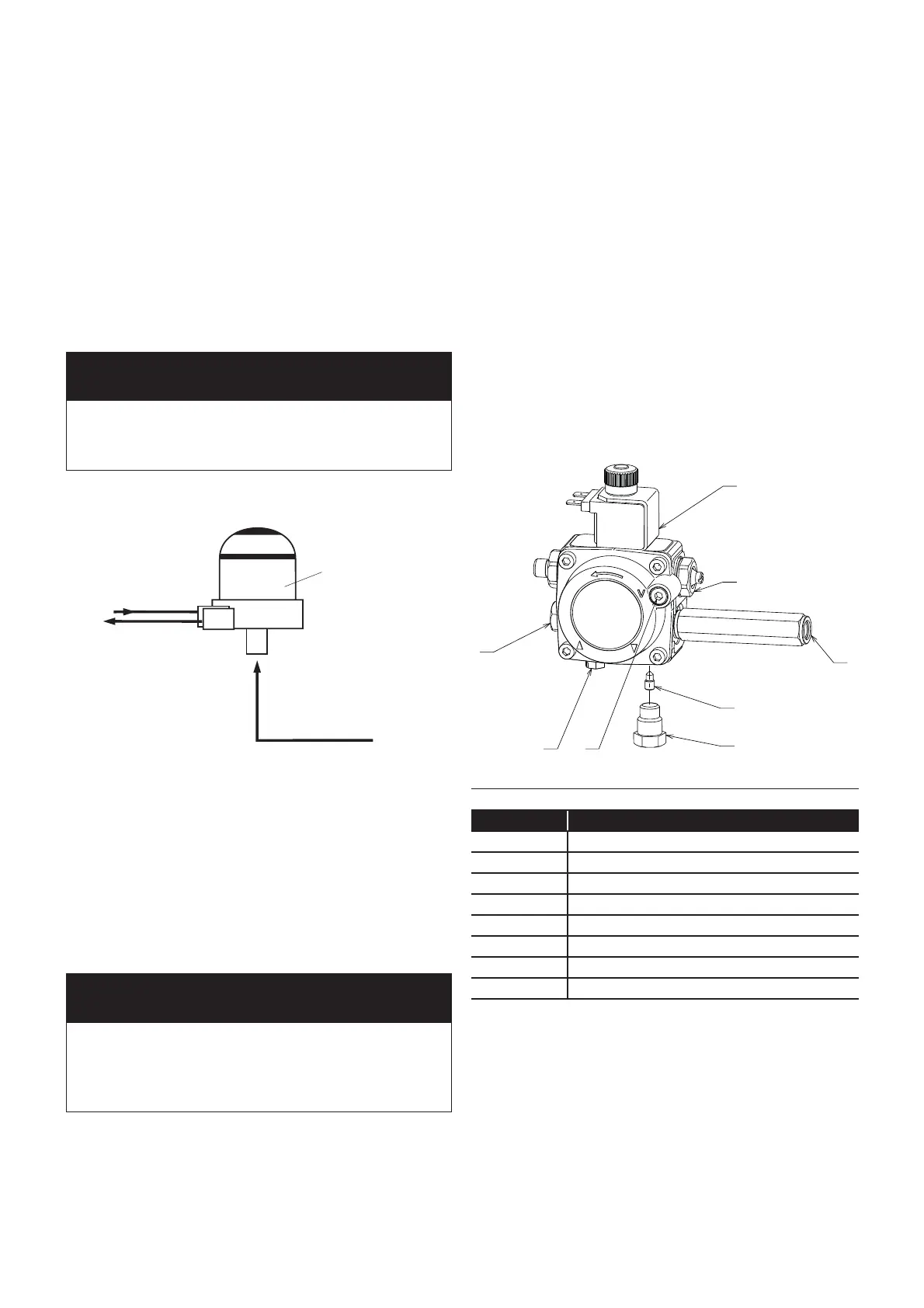
2
3
5
6
7
1
8
4
Figure 3-5: Riello RDB pump
Table 3-1: Key to Riello RDB pump
Item Description
1 Inlet (suction) port
2 Return port
3 By-pass screw
4 Pressure gauge port
5 Pressure adjustment
6 Vacuum gauge port
7 Solenoid
8 Auxiliary pressure test point