日本語
English
Français Deutsch 中文 한국어 Español
Connection Methods
4
A
B
b
b
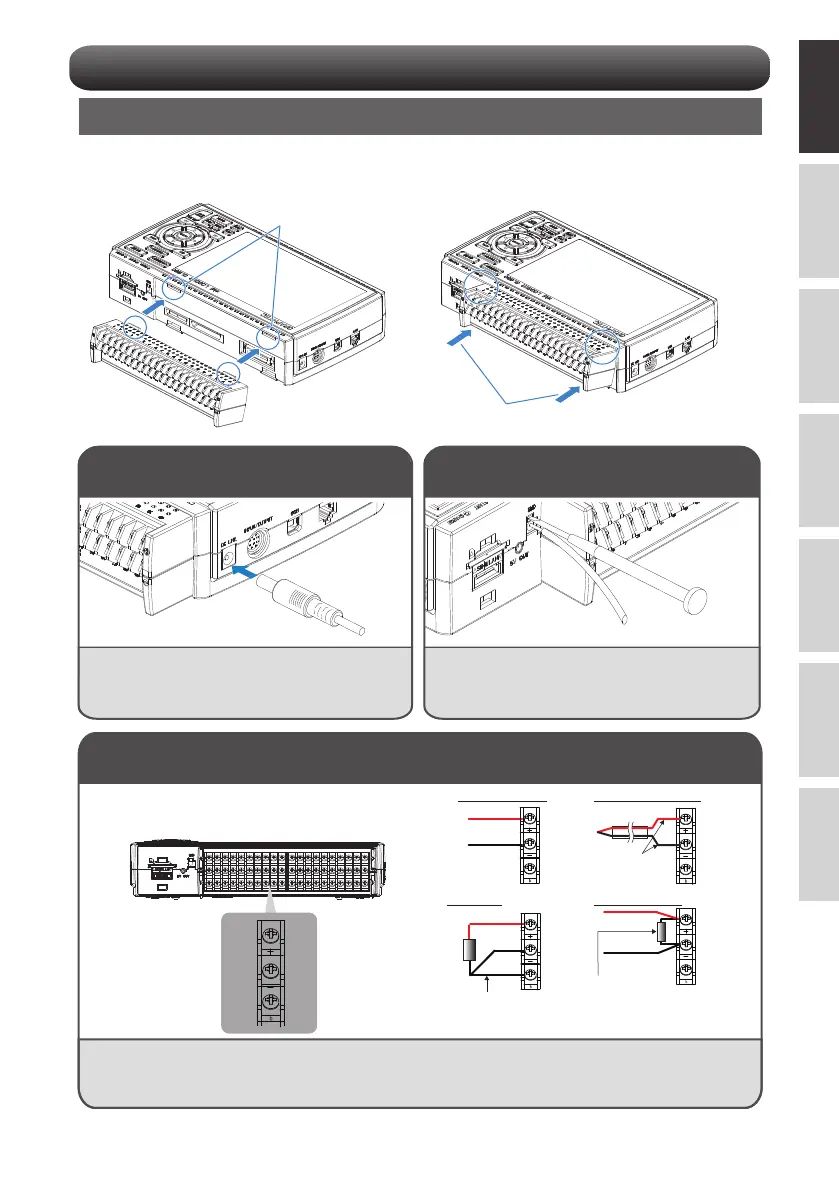
DC voltage input
Withstand high-voltage
high-precision terminal(B-565)
CH1................................CH20
Thermocouple input
RTD input DC current input
+
-
Compensation cable.
+
-
DC voltage
+
-
+
-
Lead wire resistance should
be 10 Ω or less per wire and,
three wires need to be same
length.
Shunt resister
Ex: For 4-20mA, add 250Ω (±0.1%) and
measure in the 1-5V range.
* Use B-551 (option) for the shunt resistor.
Connecting the Analog Input Terminals
CAUTION
• Connect to any terminal according to the picture above.
For the connection to the screwless terminal, refer to the instruction manual (PDF).
• B-563/B-563SL/B-563SL-30 do not support RTD input.
+
-
b
Mounting each terminal
1. Insert tabs at the top of the terminal unit into
the grooves.
2. Push the terminal unit in the direction shown
until it is securely locked.
Connect the DC output of the AC adapter to the
connector indicated as "DC LINE" on the GL860.
Use a flathead screwdriver to push the button above
the GND terminal while connecting the grounding
cable to the GL860.
Connect the other end of the cable to ground.
Connecting the AC Adapter
Connecting the Grounding Cable
Insert into grooves
Push