247Program description - Telemetry
Value Explanation
Possible settings
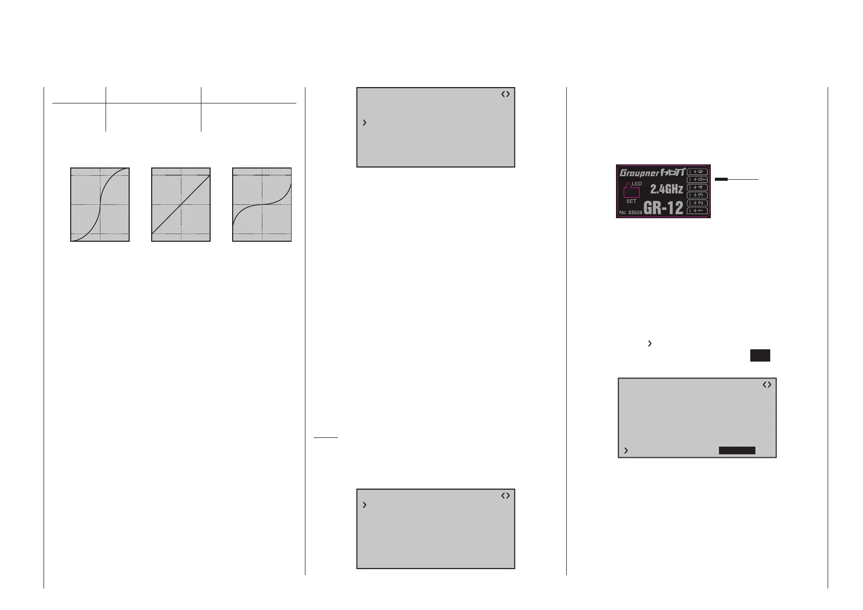
TYPE Curve type A, B, C
see figure
Expo = +100%
–100%
+100%
0
–100%
+100%
0
Expo = –100%
TYPE A
–100%
+100%
0
–100%
+100%
0
linear
–100%
+100%
0
–100%
+100%
0
TYPE B
TYPE C
DR = 125% DR = 70%
Servo travel
Control travel
Servo travel
Control travel
Servo travel
Control travel
Normally a non-linear control function, if applicable, is
used for the aileron (channel 2), elevator (channel 3)
and rudder (channel 4). These channel defaults also
correspond to the factory settings.
BUT CAUTION: This assignment only applies when,
on the transmitter side, neither “2HRSv3+8” is speci-
fied in the “Tail type” line nor is “2AIL” or “2AIL 2FL”
specified in the “Aileron/camber flaps” line of the
»Model type« menu, page 130. Otherwise, assign-
ments will have already been made in the transmit-
ter for control function 3 (elevator), which will then
be split between control channels 3 & 8, or control
function 2 (aileron), which will then be split between
control channels 2 & 5 for the left and right ailerons.
The corresponding control channels (INPUT CH) in
the receiver would in both cases be channels 03 & 08
or 02 & 05.
Therefore if, for example, “2AIL” has been specified
on the transmitter side and the intent here is to utilize
the RX CURVE option instead of the
mc-16 HoTT
or mc-20 HoTT transmitter’s individually adjustable
»Dual Rate / Expo« menu, see page 130 or 134,
then two curves must be set. Otherwise, the left and
right ailerons have different control characteristics:
RX CURVE
TYPE : A
CURVE1 CH : 02
TYPE : A
CURVE2 CH : 05
TYPE : B
CURVE3 CH : 04
With the RX CURVE function you can manage the
control characteristics for up to three servos:
• CURVE 1, 2 or 3 CH
Select the desired control channel (INPUT CH) of
the first servo.
The following setting in TYPE only pertains to the
channel selected here.
TYPE
Select the servo curve:
A: EXPO = -100 % and DUAL RATE = 125 %
The servo reacts strongly to movements of the
stick around the neutral position. As the rudder
throw increases, the curve becomes flatter.
B: Linear setting.
The servo follows the stick movement linearly.
C: EXPO = +100 % and DUAL RATE = 70 %
The servo reacts weakly to the stick movements
around the neutral position. As the rudder throw
increases, the curve becomes steeper.
Note:
The control characteristics programmed here also
affect the mapped receiver outputs.
5CH FUNCTION: “SERVO” or “SENSOR”
RX CURVE
TYPE : B
CURVE1 CH : 02
TYPE : B
CURVE2 CH : 03
TYPE : B
CURVE3 CH : 04
5CH FUNCTION:SERVO
Some receivers have a specific servo connection
which has been made switchable rather than an
independent telemetry connection. Thus, for example,
on the GR-12 receiver included with the mx-12 HoTT
set, order no. 33112, servo connector 5 has an extra
“T” mark and can be alternatively connected …
Servo
Sensor
OR
… not only via an order no. 7168.6A adapter cable
to upgrade the receiver but also connected to a tele-
metry sensor.
However, in order for the receiver to correctly recog-
nize the given connected device correctly, servo con-
nection 5 (in this case) MUST be appropriately set for
either “SERVO” or “SENSOR”.
This switchover is accomplished by moving the
with the selection key of the left or right four-way
button until the “
” symbol is at the left margin of the
bottom line then tapping on the center SET key of the
right four-way button:
RX CURVE
TYPE : A
CURVE1 CH : 02
TYPE : A
CURVE2 CH : 03
TYPE : B
CURVE3 CH : 04
5CH FUNCTION:SERVO
Now use one of the selection keys on the right
four-way button to select the alternative setting “SEN-
SOR”.

 Loading...


