30 / 36
S1033_jh_V1_de
Telemetry data display
Sensors
The upper display serves as graphical representation of the
telemetry data.
If a receiver is bound the telemetry display appears. By tipping
again the selection keys
, you can select which sensor or
module you want to be displayed.
If instead there are two "X" instead of
in the lower part of
the display and it appears the message "CAN'T RECEIVE ANY
DATA", it means that there is no connection between receiver
and transmitter and that no telemetry data is available. Turn on
your receiver, or bind a receiver to the active model memory.
Depending on the connected modules and sensors, several
selectable displays will appear. The description of these displays
is contained in the manual included in the sensor package.
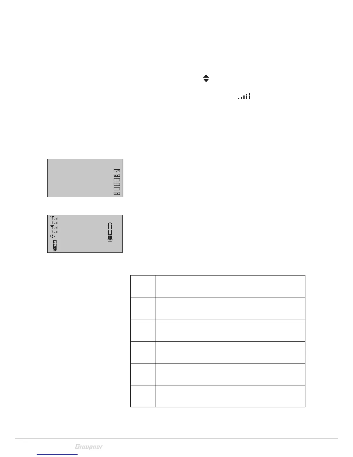
The transmitter recognizes automatically the sensors. You can
view the sensors by changing from the main menu to the telem-
etry menu. The sensors will be listed in the display and marked
with a check mark.
Receiver
This display offers a graph of the data from the display "RX DAT-
AVIEW“ of the "Telemetry" menu "SETTINGS, DISPLAYS".
Value Explanation
RX-S
QUA
Quality expressed as a percentage of the signal packages from
the transmitter arriving at the receiver
RX-S ST Signal strength expressed in percentage of the signal from the
transmitter arriving at the receiver
RX-dBm Level in dBm expressed as the percentage of the transmitter
signal arriving at the receiver
V PACK Level in dBm expressed as the percentage of the receiver
signal arriving at the transmitter
TX-dBm Shows the longest time in ms in which the data packets are
lost during a transmission from the transmitter to receiver
RX-VOLT Current operating voltage of thereceiver power supply in Volts
SENSOR SELECT
RECEIVER
GENERAL MODULE
VARIO MODULE
ELECTRIC AIR MOD.
GPS
ESC
RX–S QUA: 100%
RX–S ST.: 100%
TX–dBm: – 33dBm
RX–dBm: –33dBm
RX–SPG.:4.8V TMP
V–PACK: 10ms
CH OUTPUT TYPE:ONCE
M–RX V :4.6V +22°C

 Loading...