32
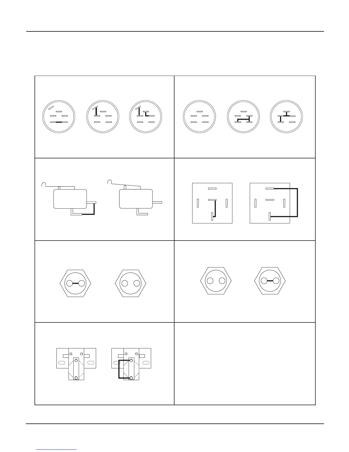
CONTINUITY DIAGRAM
Model 985114, 115, 117, 119, 307, 309, 311, 312, 313
PH0421
OFF
M
G
S2
B
S1
A
RUN
M
G
S2
B
S1
A
START
M
G
S2
B
S1
A
Key Switch (115, 117, 119, 307, 309, 311, 312, 313)
(03602300)
DISENGAGED
(button in)
Handlebar and Steering Brake Switch
(046823)
1
2
HAND
ON HANDLE
1
2
HAND
OFF HANDLE
PTO Switch
(051918)
ENAGED
(button out)
1
2
1
2
Forward/Reverse Switch
(051919)
1
2
1
2
NEUTRAL
(button out)
FORWARD OR REVERSE
(button in)
Solenoid
(044766)
NOT ENERGIZED ENERGIZED
Relay
(040216)
87
87A
86 85
30
NOT ENERGIZED
87
87A
86 85
30
ENERGIZED
OFF
A
S
R
B
RUN
A
S
R
B
START
A
S
R
B
Key Switch (114)
(019223)
The diagrams below show the various states of connection for electrical components.
The solid lines on switches show continuity.
NOTE: All switches are viewed from the rear.