HackRF
18.6 Identify the pin headers
Firstly, this has only been tested on official HackRF Ones. If you have a jawbreaker, HackRF blue or another HackRF-
inspired device, you will have to figure out how to connect the devices correctly, using the schematics.
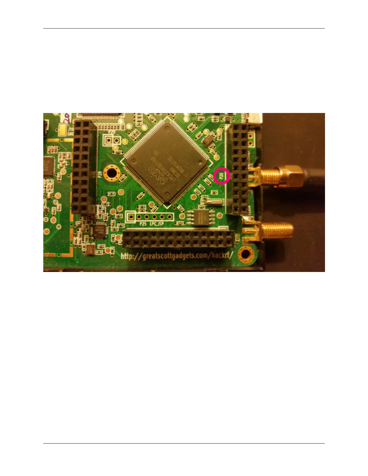
The hackrf has four pin headers, three of which are arranged in a ‘C’ shape. On the board these are marked as P28, P22
and P20. P20 is the header closest to the clock in/clock out connectors. For this exercise we will only be discussing
P20. The hackrf schematics are a very good reference for this activity. The relevant part can been seen in the following
image:
This is the P20 schematic diagram:
18.6. Identify the pin headers 55