HackRF
18.7 Wire up the pin headers
As mentioned before BE WARNED, this step could easily result in one or all of your HackRFs being permanently
damaged.
Now that’s out of the way, let me describe what we’re doing here. The first part of this exercise is to give both devices
a common ground. This is really important for any inter-device electrical connections, as it prevents ICs from seeing
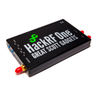
slight differences in the respective GND levels as legitimate signals. As shown on the schematic, many of the pins in
P20 are GND pins. We use P20-PIN19 on both devices and connect them together like so:
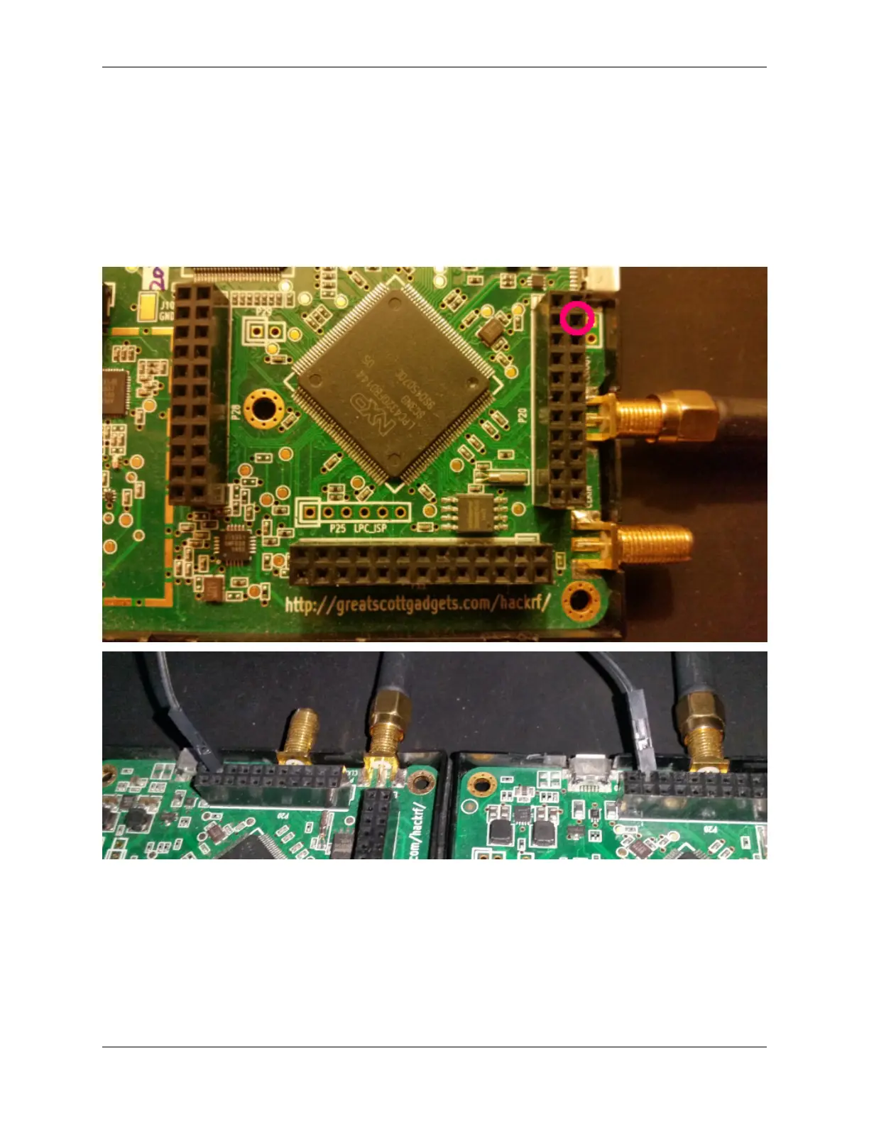
We then need a positive (+5v) connection to ‘fake’ the third hackrf if it’s not present. We use P20-PIN3 from the
primary hackrf for this, and bring it down to the breadboard. primary:P20-PIN8 and secondary:P20-PIN8 are ready
input GPIO pins for the missing third HackRF. Connect these to the breadboard positive line. After this your setup
should look like so:
18.7. Wire up the pin headers 57