GMV5 D.C INVERTER MULTI VRF SERVICE MANUAL
163
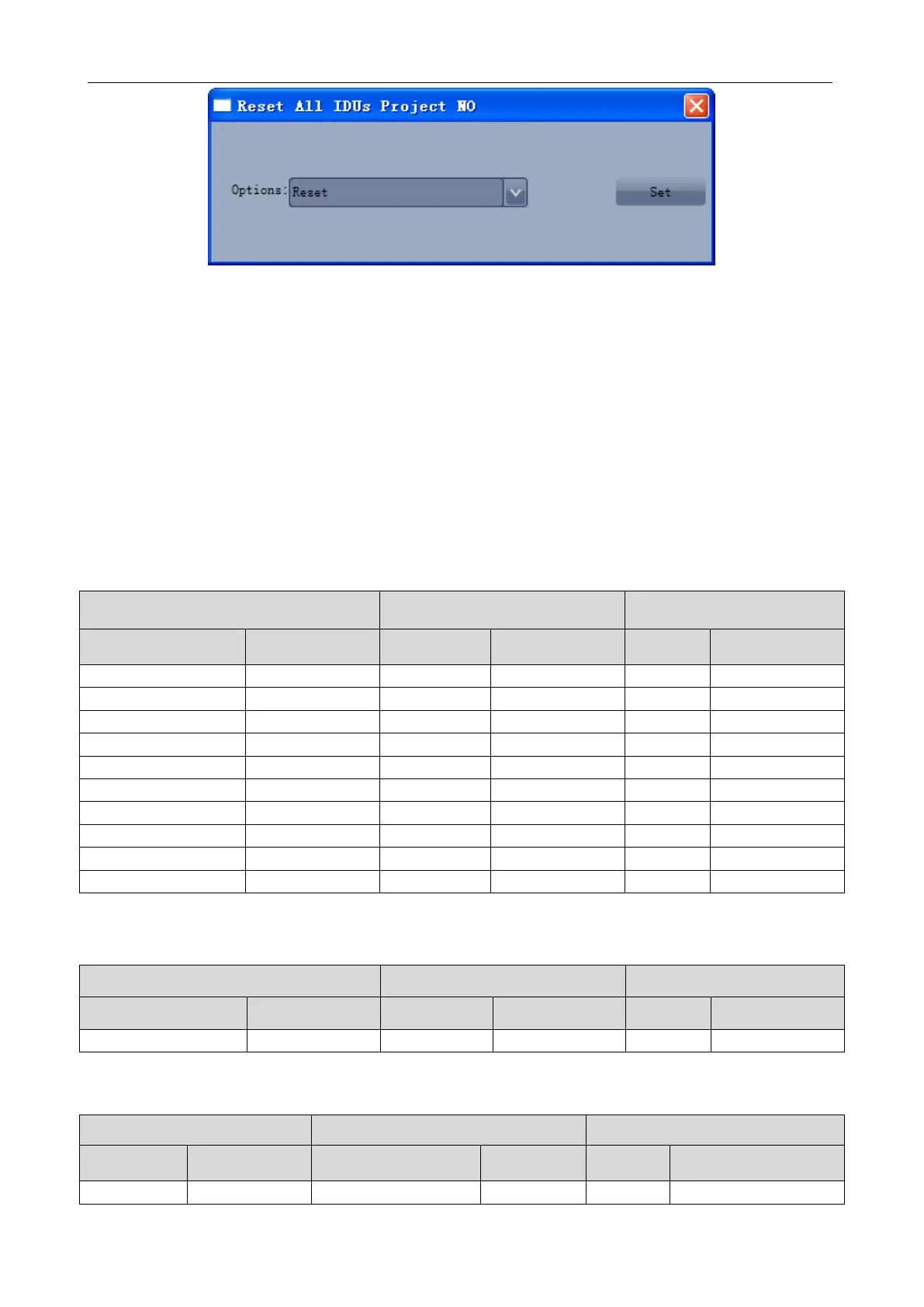
Figure 7
If the conflict is solved, the system will return to the normal status and IDUs can be operated as
shown in Figure 5.
①
Manual setting on the communicator and remote controller:
When the project number conflict occurs, you can use the communicator or remote controller to
revise project numbers and solve the conflict. See the manual of the communicator or remote controller
for the method.
②
Setting of auto project number deviation on ODU's main board (recommended)
You can set auto IDU project number deviation via the ODU's main board as follows:
(1) After the whole system is commissioned, short press SW3 on the controlling unit and the system
will enter the standby status as follows:
(2) Press SW2 (▼) on the controlling unit and select n5. Short press SW7 to show the following
information:
(3) When project number deviation is to be confirmed, short press SW7 confirmation button to enter
the project number deviation status as shown in the following:
 Loading...
