DC Inverter Multi
VRF Service Manual
165
6�3 Debugger Connection
6.3.1 Power Supply and Communication Interface
4-core port includes power supply and communication.
There are two connecting methods:
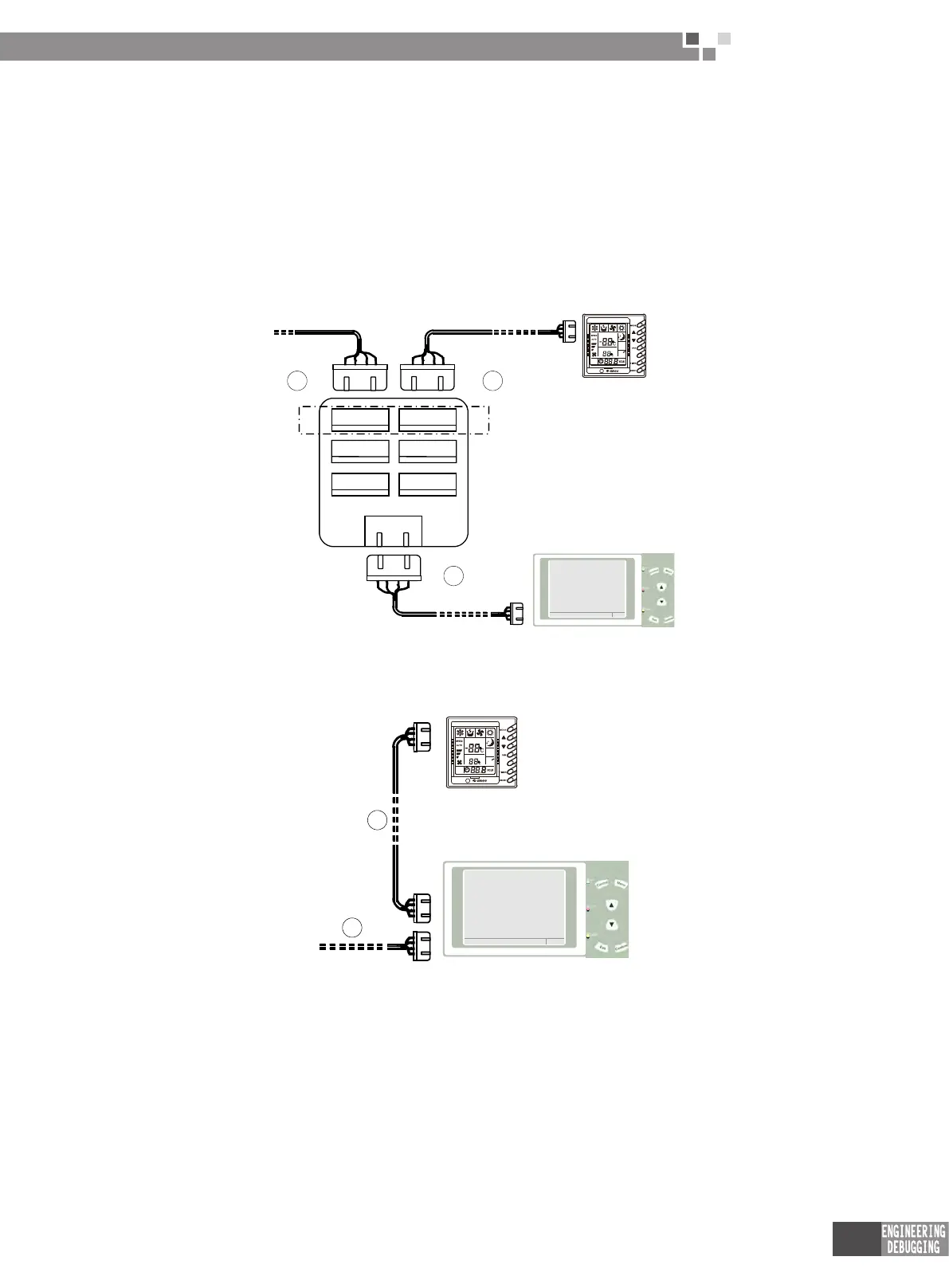
1) Wiring method 1 of portable debugger:
Step 1: Remove the display panel and insert its 4-core port into pinboard COM1.
Step 2: Connect pinboard COM1 to the display panel with the 4-core wiring.
Step 3: Connect pinboard COM4 to debugger COM1 with the 4-core wiring.
1 2
3
COM1COM2COM3
COM1 COM2
COM3
COM4
[VERSION V1.3]
MUNE
<MENU> OPEN MENUPAGE
28-10-2009 TUE 2 1:45:60
PORTABLE DEBUGGER
ROOM TEMP
SWING
SET TEMP
MELT
SWING
2) Wiring method 2 of portable debugger:
Step 1: Remove the display panel and insert its 4-core port into debugger COM1.
Step 2: Connect debugger COM2 to the display panel with the 4-core wiring.
ROOM TEMP
SWING
SET TEMP
MELT
SWING
1
2
[VERSION V1.3]
MUNE
<MENU> OPEN MENUPAGE
28-10-2009 TUE 21:45:60
PORTABLE DEBUGGER
 Loading...