194
DC Inverter Multi
VRF Service Manual
3 POWER DISTRIBUTION
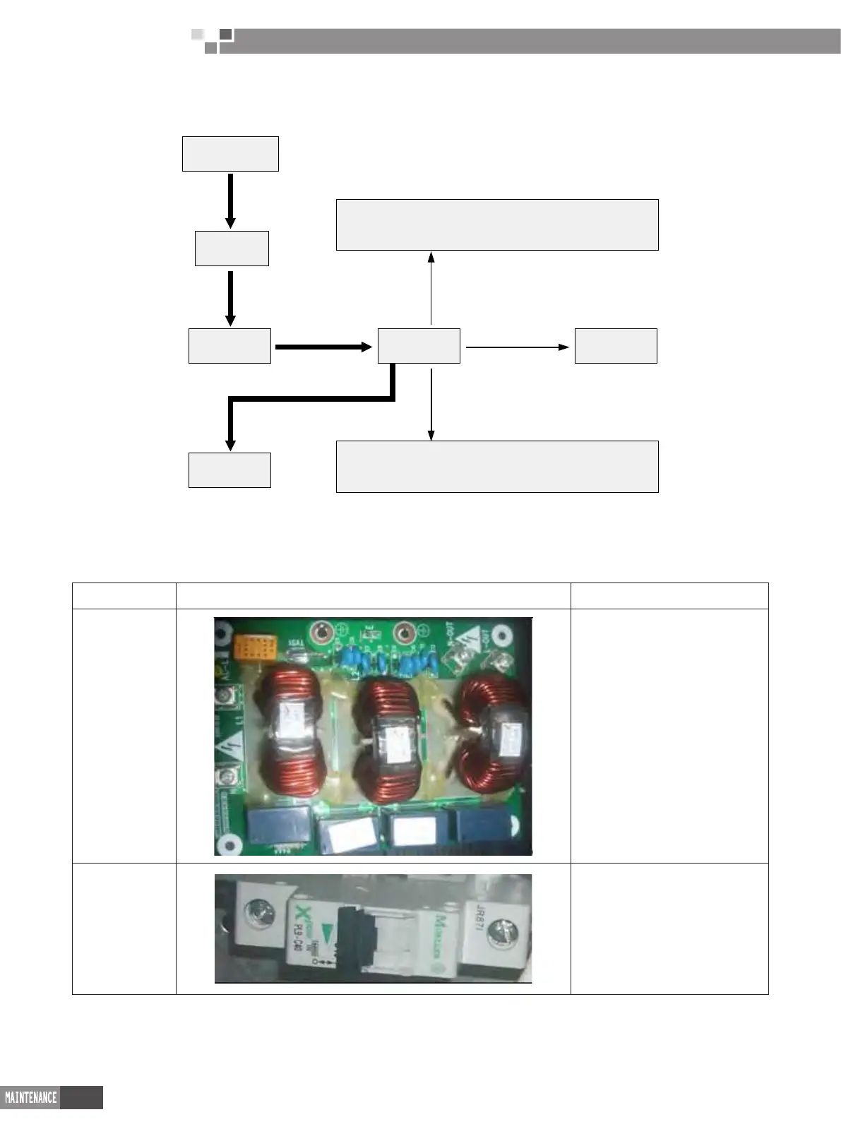
3�1 Diagram of Power Distribution
Power Supply
Air switch
Filter board
Mainboard
Indoor unit
Control signal of temperature sensor, electronic
expansion valve, high and low pressure switch ect.
Control signal of 4-way valve, gas bypass,
electric heating tape ect.
Compressor
(The thick lien represents power line while thin line represents the control line.)
3�2 Introduction of Main Electric Parts of Inverter System
Name Photo Introduction
Wave lter
It is mainly used for ltering the
intererence of the power supply and
prevent the unit from interfering the
power supply so that the operation
of the unit will not affect the other
electric appliances such as TV.
Air switch
Connect or disconnect the main
circuit,; with overcurrent and
short circuit protection function
 Loading...