20
DC Inverter Multi
VRF Service Manual
CONTROL
CONTROL
1 CONTROL OF THE UNIT
1�1 Concept of Integral Control of the Unit
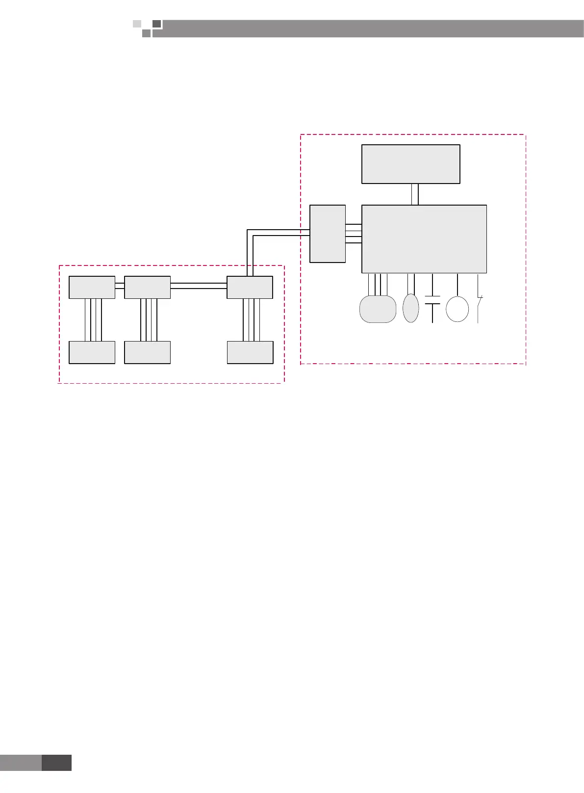
1.1.1 Unit Control Schematic Diagram
Mainboard of
indoor unit
Mainboard of
indoor unit
Display board
of indoor unit
Indoor unit, a maximum of 16 sets to be connected
Outdoor Unit
Electronic
expansion
valve
Relay output
control
High and low
pressure switch
protection input
Main control board of outdoor unit
Adap for
board
Inverter drive control system
Mainboard of
indoor unit
Display board
of indoor unit
Indoor unit n+1 Indoor unit n
Display board
of indoor unit
Indoor unit 1
4 - core
communication
cable
2 - core communication cable
3 - core pin header
Temperature sensor
Air conditioning units can be divided into indoor unit and outdoor unit. A maximum of 16 sets of indoor units can
be connected to an outdoor unit. 2-core (3-core pin header) communication cable is used for the connection between
indoor unit and outdoor unit. Indoor unit is connected to display board via 4-core communication cable. In engineering
installation, address dial-up of the display board and the mainboard of indoor unit shall be dialed. The address dial-up of
the mainboard of indoor unit must be identical with that of the display board of the same indoor unit. Address dial-up of
different indoor unit must vary. Multi VRF indoor unit is applicable to all digital or inverter outdoor units.
Controller of outdoor unit falls into two categories in terms of its function, i.e. main control system and inverter drive
control system
1.1.2 DC Inverter Unit
1) Main control system
A. Functions: main control system shall be connected to indoor unit through 2-core (3-core pin header)
communication cable in order to receive start or stop commands, mode, setting temperature and ambient temperature
from indoor unit, determine operation mode of outdoor unit, and through calculation based on capacity, decide proper
running frequency which shall be sent to the drive control system through 2-core (3-core pin header) communication cable.
Fan speed shall be regulated according to system pressure. Real-time monitoring of temperature sensors, operation state
and protection of unit shall be performed to ensure normal and stable operation of the whole system. Protection codes
of outdoor unit shall be displayed on the LED on the main control board when failure occurs. When drive is at fault, E5
shall be displayed on the display board of indoor unit, and specic failure type shall be indicated on the LED on the main
control board of outdoor unit.
B. Input and output controlled variables
Sensors include ambient temp. sensor, tube-inlet temp. sensor, tube-middle temp. sensor, tube-outlet temp. sensor,
compressor exhaust temp. sensor, compressor casing top temp. sensor, high pressure sensor and low pressure sensor.
Switch protection: high pressure protection, over-current protection
Output control objects: fan frequency, compressor heat tape (controlled by drive board), compressor AC contactor
(3-phase, controlled by drive board), gas bypass valve, 4-way valve, solenoid valve A, oil equilibrium valve, liquid bypass
valve and capillary solenoid valve.
 Loading...