44
DC Inverter Multi
VRF Service Manual
CONTROL
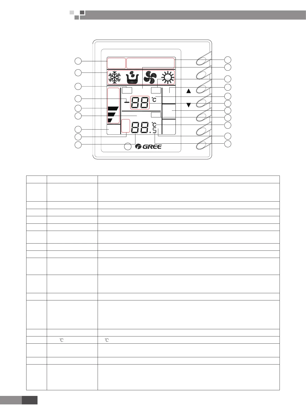
4�3 Display View
SINGLE
FORCE
MELT
AUTO
FUNC
MODE
FAN
SWING
TIMER
ON/OFF
TIMER
SWING
ON OFF
FAN
SPEED
ERROR
SHEILD
SET
ROOM TEMP
INQUIRY
CENTER
1 2 3 4 5 6 7 8
9 10 11 12 13 14 15 16
LOCK
HR
1
2
3
4
5
6
7
8
9
10
11
12
13
14
15
16
17
18
19
20
Fig.4.3
No. Display name Instruction to display
1 Control mode
Inquiry state, “INQUIRY” is displayed.
Single control state,”SINGLE” is displayed.
Centralized control state, “CENTER” is displayed.
2 Running mode Each indoor unit running mode is displayed.
3 Error “ERROR” is displayed during any malfunction to indoor or outdoor unit in a group.
4 - “-” is displayed when there is no malfunction to selected indoor unit and the ambient temp. is below zero.
5 Fan speed display Hi, mid, low or auto speed of indoor fan is displayed.
6 Set
“SET” blinks when the unit is on and commanded.
“SET” is displayed when the unit is on without command.
7 Swing Swing running of indoor unit is displayed.
8 Timer “TIMER ON/OFF” is displayed when setting timer or inquiring timer state.
9
Setting temp. and
timer time
During timer inquiry, integer of setting time of timer is displayed.
During timer setting, integer of setting time of timer is displayed.
Set temp. value is displayed when the unit is not during timer inquiry or setting.
10 No. of indoor unit
Under inquiry state, No. of online indoor units are displayed and No. of selected indoor unit will blink.
Under single control state, only No. of selected indoor unit is displayed.
Under centralized state, No. of all online indoor units are displayed.
11 Room temp. “ROOMTEMP” is displayed for no malfunction, but isn’t for malfunction.
12 Shield
Centralized controller
A. Under inquiry state,” SHIELD” will be displayed when selected indoor unit is shielded.
B. Under control state,” SHIELD” will be displayed during setting or giving the shield order.
Region wired controller:” SHIELD” will be displayed when selected
units are shielded during long-distance monitoring.
13 Force “FORCE” is displayed when indoor unit is forced to run.
14
(room temp.) “ ” is displayed when there is no malfunction.
15 Room temp. or error code
Room temp. value is displayed during no malfunction to selected indoor or outdoor unit.
Error code is displayed during malfunction to selected indoor or outdoor unit.
16 Melt “Melt” is displayed during defrosting.
17 Lock
Region monitoring controller
A: Inquiry state: “LOCK” is displayed when selected indoor unit is locked.
B: Control state: “LOCK” is displayed during setting or giving the lock order.
Region wired controller: “LOCK” is displayed when selected unit is locked in long-distance monitoring.
 Loading...