68
DC Inverter Multi
VRF Service Manual
CONTROL
6�3 Connection Between Controller and Unit
Communication network
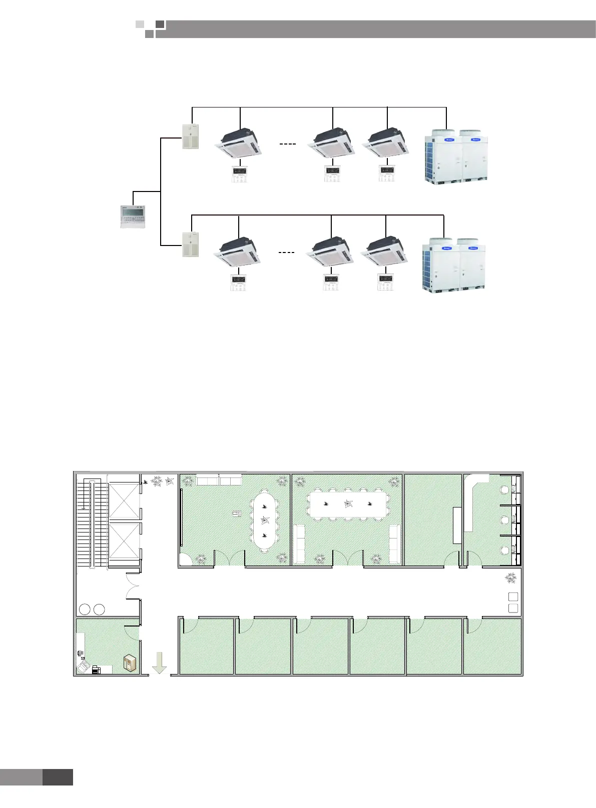
The following is a brief sketch of communication net of multi variable units:
Communication
module1
Indoor
control
Indoor
control
Outdoorunit
Centralcontrol
(The max. of N is 64)
Outdoorunit
Communication
module1
Fig.6.1.4
As shown in gure, the ”\” at A are parting lines for communication net. Left side of the “\” is the communication
net between central control and communication module while the right side is that between multi variable outdoor unit and
indoor units. The 2 nets are individual nets.
Before normal use of central control, do conduct addresses setting and adjusting to communication system by
installation personnel. Only after that can the central control offered to be used by user.
6�4 Case Study
Take one oor of an ofce building for example to illustrate wiring and debugging of the centralized control system.
In this oor, there are 2 assembly rooms, 8 ofces and 1 monitor room. Refer to the following illustration for its plane
structure.
上
Office
48 sq m
25 sq m
15 sq m
办公室
48 sq m
17 sq m
WC
Assembly Room No.1 Assembly Room No.2 Office No.7Office No.8
Office No.6
Office No.5
Office No.4
Office No.3Office No.2Office No.1
Monitor Room
Office
25 sq m
Office
Office Office
15 sq m
Office
15 sq m
Office
15 sq m
Office
15 sq m
Office
15 sq m
Office
Fig.6.5
 Loading...