Securing the Damper/Sleeve Assembly to Wall/Floor Openings cont.......
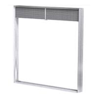
Grille Installations (Dampers up to 36 in. x 36 in. [914mm x 914mm])
Retaining angles used in conjunction with grille installations must be a minimum of
5
⁄8 in. x 1 in. (15mm x 25mm)
16 gauge (1.5mm) steel. Space screws a maximum of 6 in. (152mm) O.C. and a maximum of 2 in. (51mm) from the
corners (minimum of 2 screws per side). See Figure 12 and Figure 13.
Note: Screws used to attach grille are allowed to penetrate reversed angle leg.
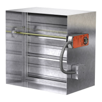
Damper
Sleeve
Angle Fastener
Grille (supplied
by others)
#10 sheet metal screws
spaced 6 in. on center
and a maximum of 2 in.
from the corners
(minimum of 2 screws per
side). Screw into studs so
as to avoid space
conflicts with the grille
Stud or Runner
Retaining Angle/Flange
Two layers of 1/2 in.
UL Classified Gypsum
Wallboard for 2 hour
rated walls. One layer
for 1 hour rated walls
(see UL Rated Wall
Design for Additional
Details).
Figure 13: Metal Stud - Grille
Two layers of 1/2 in. UL
Classified Gypsum
Wallboard for 2 hour
rated walls. One layer for
1 hour rated walls (see
UL Rated Wall Design for
Additional Details).
Grille (supplied by others)
Retaining Angle
Angle Fastener
Damper Sleeve
#10 sheet metal screws, 2
1/2 inches long, spaced 6
in. on center and a
maximum of 2 in. from the
corners (minimum of 2
screws per side). Screw
into studs so as to avoid
space conflicts with the
grille.
2 1/2 in. minimum
Stud or Runner
Figure 12: Wood Stud - Grille
Figure 14: Damper/Sleeves with Transition
Factory or Field installed Sleeve
1/4 in. minimum
total clearance
Wall or Floor
Maximum
6 in.
Maximum
6 in.
Duct
Damper
Damper
Damper
Wall or Floor
Wall or Floor
Retaining Angles
Type A
Type B
On types R, CO & CR factory
furnished duct collar
qualifies as breakaway
connection.
Type C, CO, CR, & R
Factory Sleeve
Wall or
Floor
Retaining Angles
Sleeve
Duct
“K” side
Damper
Max. 6 in.
Max. 6 in.
Factory Sleeve
1/4 in. minimum
total clearance
Wall or Floor
Maximum
6 in.
Maximum
6 in.
Duct
Duct
Duct
Damper
Wall or Floor
Retaining Angles
Type A
Type B
On types R, CO & CR factory
furnished duct collar
qualifies as breakaway
connection.
Type C, CO, CR, & R
Factory Sleeve
Type B2
Wall or floor
Damper
Sleeve
Field Installed Sleeve
Damper
1/4 in. minimum
total clearance
(See Section 1)
Maximum
6 in.
Maximum
6 in.
Wall or floor
Wall or floor
Wall or floor
Damper
Damper
Duct
Duct
Duct
Retaining Angles
(See Section 4)
Sleeve
(See Sleeve Requirements)
Sleeve
Sleeve
On types R & CR factory
furnished duct collar
qualifies as breakaway
connection (See Connecting
Ducts to Fire Damper Sleeve)
1 in. min.
overlap
Four sides
Mounting Angles
(See Para. 4)
1/4 in. minimum
total clearance
(See Para. 1)
Retaining angle leg
shall not exceed 7 in.
(178mm)
Type A
Type B
Type C, CO, CR & R
Field installed Sleeve
Damper
1/4 in. minimum
total clearance
(See Section 1)
Maximum
6 in.
Maximum
6 in.
Wall or floor
Wall or floor
Wall or floor
Damper
Damper
Duct
Duct
Duct
Retaining Angles
(See Section 4)
Sleeve
(See Sleeve Requirements)
Sleeve
Sleeve
On types R & CR factory
furnished duct collar
qualifies as breakaway
connection (See Connecting
Ducts to Fire Damper Sleeve)
1 in. min.
overlap
Four sides
Mounting Angles
(See Para. 4)
1/4 in. minimum
total clearance
(See Para. 1)
Retaining angle leg
shall not exceed 7 in.
(178mm)
Type A
Type B
Type C, CO, CR & R
8
Curtain Fire Dampers