Centrifugal Inline Fans 9
®
Maintenance
Installation and maintenance are to be performed only
by qualified personnel who are familiar with local codes
and regulations and who are experienced with this type
of equipment.
Motor maintenance is generally limited to cleaning
and lubrication (where applicable). Cleaning should be
limited to exterior surfaces only. Removing dust buildup
on motor housing ensures proper motor cooling.
Greasing of motors is only intended when fittings are
provided. Many fractional horsepower motors are
permanently lubricated and should not be lubricated
after installation. Motors supplied with grease fittings
should be greased in accordance with manufacturers’
recommendations. Where motor temperatures do not
exceed 104ºF (40ºC), the grease should be replaced
after 2,000 hours of running time as a general rule.
Wheels require very little attention when moving clean
air. Occasionally, oil and dust may accumulate causing
imbalance. When this occurs the wheel and housing
should be cleaned to ensure smooth and safe operation.
All fasteners should be checked for tightness each
time maintenance checks are performed prior to
restarting unit.
A proper maintenance program will help these units
deliver years of dependable service.
DANGER
Always disconnect, lock and tag power source before
servicing. Failure to disconnect power source can
result in fire, shock or serious injury.
DANGER
Pour écarter les risques d’incendie, de choc électrique
ou de blessure grave, veiller à toujours débrancher,
verrouiller et étiqueter la source de courant avant
l’installation ou l’entretien.
IMPORTANT
Uneven cleaning of the wheel will produce an out of
balance condition that will cause vibration in the fan.
WARNING
This unit should be made non-functional when
cleaning the wheel or housing (fuses removed,
disconnect locked off).
AVERTISSEMENT
L’appareil doit être rendu non opérationnel lors du
nettoyage de la turbine ou du caisson (fusibles retirés,
sectionneur verrouillé).
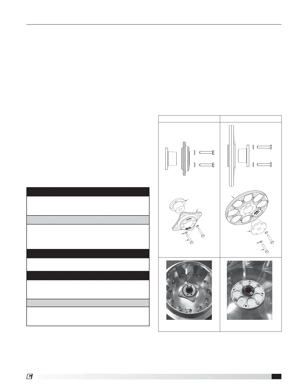
Tapered Bushing Hub Installation
and Removal
For wheel hubs and shaft pulleys utilizing a tapered
bushing interface, follow this procedure for installation
and removal. There are two possible set ups for the
tapered bushing, both have the same procedure, but
orientation of the hub varies.
Tapered Bushing Removal
1. If present, loosen the setscrew holding the bushing
and shaft key in place.
2. Loosen and remove the socket head cap screws
which fasten the bushing to the hub as shown in the
section views and examples of Figures 14-17.
Standard Mounting Reverse Mounting
Figure 16
Standard Bushing Orientation
Figure 17
Reverse Bushing Orientation
Figure 14
Figure 15
Bushing
Washers
Cap Screws
Hub
Bushing
Washers
Cap Screws
Hub