Clearances Required Between Damper Sleeves & Wall/Floor Openings
Two-Sided Angle Installation
Two-sided angle installations require clearances for thermal expansion between the damper sleeve and the wall/floor
opening. The minimum required clearances are:
• For galvanized steel dampers and sleeves:
1
⁄8 in. per foot (3mm per .3 m) of damper width and
1
⁄8 in. per
foot (3mm per .3 m) height with a minimum clearance of
1
⁄4 in. (6mm). The total gap may be up to 6 in.
(152mm), 3 in. (76mm) per side, as long as the retaining angles overlap the wall/floor by a minimum of 1 in.
(25mm).
• For stainless steel dampers and stainless steel or galvanized sleeves:
3
⁄16 in. per foot (5mm per .3 m) of
damper width and height with a minimum clearance of ¼ in. (6mm), maximum of 2 in. (51mm).
These are total clearances (ignoring fastener heads) and do not need to be equally spaced around the damper.
Although the minimum requirements are listed above, for ease of installation the following are the recommended
clearances for galvanized dampers:
• Width/Height of 48 in. (1219 mm) or less - ½ in. (13mm) clearance
• Width/Height between 48.01 in. (1220 mm) and 96 in. (2438 mm): 1 in. (25mm) clearance
• Width/Height greater than 96 in. (2438 mm): 1½ in. (38 mm) clearance
Example:
A 12 in. x 12 in. (305mm x 305mm) will
require a minimum clearance of ¼ in.
(6mm) width and ¼ in. (6mm) on height
A 48 in. x 12 in. (1219mm x 305mm)
damper will required a minimum
clearance of ½ in. (13mm) on width and
¼ in. (13mm) on height.
Single Side Angle Installation
On vertical mount single side angle installations there are no minimum clearance requirements between the wall
opening and the damper sleeve. However, to facilitate installation, clearances between the wall opening and the
damper sleeve are recommended.
On horizontal mount single side angle installations a minimum clearance is required between the outside of the
damper sleeve and the floor opening of
1
⁄8 in. per foot (3mm per .3m) of damper width and
1
⁄8 in. per foot
(3mm per .3m) height with a minimum clearance of ¼ in. (6mm).
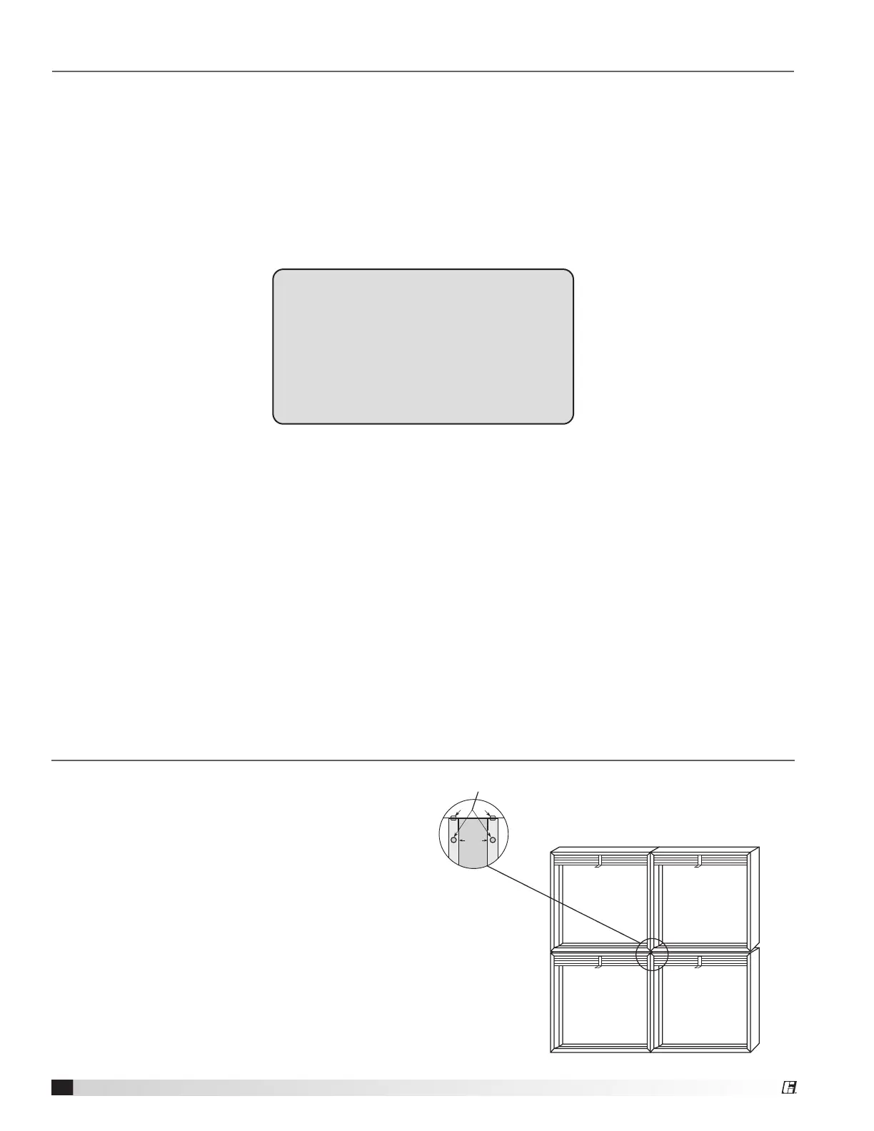
Installing Multiple Section Assemblies
A damper assembly is not restricted to a maximum
number of sections, but must not exceed the section
sizes and overall sizes shown (see chart below).
The damper sections must be attached together with
#10 (¾ in. max. [19mm]) sheet metal screws, ¼ in.
(6mm) diameter nuts and bolts, tack or spot welds, or
3
⁄16 in. (48mm) diameter steel pop rivets. Attachments
must be spaced a maximum of 6 in. (152mm) O.C. and
a maximum of 2 in. (51mm) from corners. Attachments
must be made on front face and back face (air entering
and air exiting side) of damper sections.
Attachments--Do not
place attachments
between blade channels
Blade
Channel
Figure 5
4
Curtain Fire Dampers