Securing the Damper/Sleeve Assembly to Wall/Floor Openings
All fire and combination fire smoke dampers may utilize the two sided angle installation method described below.
1
1
⁄2 hour rated fire and combination fire smoke dampers may use the single sided angle installation method up to the
following maximum sizes:
• Vertical mount: 80 in. W x 50. in. H (2032mm W x 1270mm H), 50 in. W x 80 in. H
(1270mm W x 2032mm H), or 40 in. W x 100 in. H (1016mm W x 2540mm).
• Horizontal mount: 144 in. W x 96 in. H (3658mm W x 2438mm H)
• Retaining Angle Gauge: Retaining angles for 1½ hour rated dampers with a width and height 48 in. (1219mm)
or less must be a minimum of 20 ga. (1mm). Retaining angles for all 3 hour rated dampers and all dampers with a
width or height greater than 48 in. (1219mm) must be a minimum of 16 ga. (1.5mm).
• Retaining Angle Size: The leg of the retaining angle on the damper sleeve shall be a minimum of 1¼ in. (32mm).
The leg of the retaining angle on the wall/floor shall be long enough to cover the annular space and overlap the
wall/floor by a minimum of 1 in. (25mm).
• Retaining Angle Attachment to Sleeve: Retaining angles must be attached to the damper using one or more of
the following methods of attachment (refer to label on outside of sleeve for ‘No Screw’ area):
- Tack or spot welds
- #10 (
3
⁄4 in. [19mm] max.) sheet metal screws
-
1
⁄4 in. (6mm) bolts and nuts
-
3
⁄16 in. (5mm) steel pop rivets
A minimum of two connections per side, top, and bottom, spaced 12 in. (305mm) O.C. maximum are required for
openings of 48 in. W x 36 in. H (1219mm x 914mm) and less. Dampers greater than 48 in. wide (1219mm) or 36 in.
high (914mm) require the connections to be no more than 6 in. (152mm) O.C..
The angles must be attached to all 4 sides of the sleeve. Ensure that fasteners do not interfere with the operation of
the damper. The angles need not be attached to each other at the corners.
• Retaining Angle Attachment to Wall/Floor:
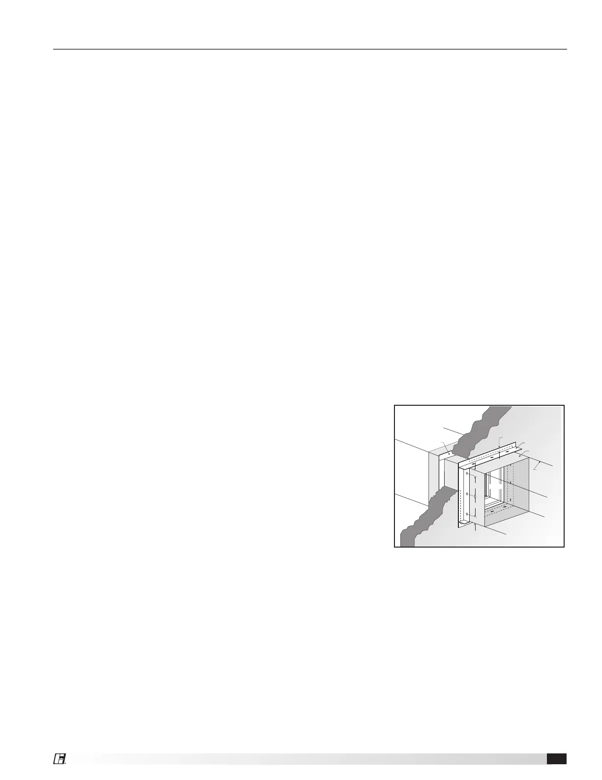
Two-Sided Angle Method: For two-sided angle installations the
retaining angles shall not be attached to the wall/floor (see
Figure 9).
Single Sided Angle Method: For single side installations the
retaining angles must be attached to the wall/floor
(see Figures 10-13). For metal stud partitions only, the single side
mounting angle may be directly attached to the metal stud prior to
the installation of the drywall.
• Retaining angles must be attached to the partition using one
of the methods shown below:
- Drywall screws of a length such that the screw
engages the steel stud/track by ½ in. (13mm) (steel
framing).
- Drywall screws of a length such that the screw
engages the wood stud by 1¾ in. (44mm) (wood
framing).
- Steel anchors or self tapping concrete screws penetrating masonry or block 1¼ in. (31mm).
• A minimum of two connections per side are required. Additional connections made at a maximum
of 12 in. (305mm) O.C. for openings of 48 in. W x 36 in. H (1219mm x 914mm) and less. Dampers
greater than 48 in. wide (1219mm) or 36 in. high (914mm) require the connections to be no more than
6 in. (152mm) O.C.
2 in. M ax.
6 in. M ax.
Sleeve
Retaining
Angle
Damper
Duct
Min. 1 in.
Overlap*
Wall or
Floor
Retaining
Angle
*only applicable for damper sizes above 36 in. x 36 in.
6 in. M ax.
2 in. M ax.
Figure 9: Two-sided angle
installation method
Multi-Blade Fire and Combination Fire Smoke Dampers 7