Upblast Centrifugal Roof Exhaust4
®
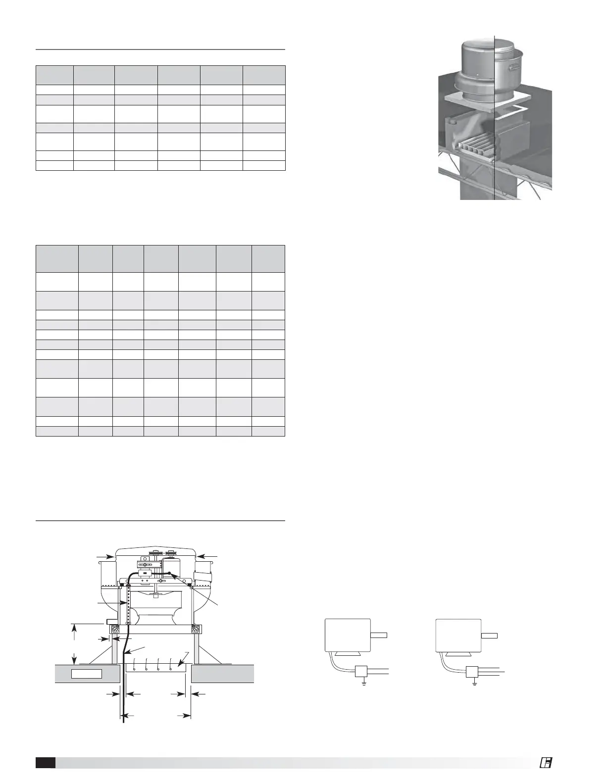
Installation
General Ventilation Installation
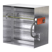
Figure 4 - Typical Roof Mounting Installation
8 or 12 in. min.
(203 or 305 mm)
Recommended
Roof Opening
Recommended
Duct and
Damper Size
Wiring by
Others
Factory Wired
Motor to
Disconnect
Roof Deck
Damper
Screw
Screw
Conduit
Chase
3/4 in.
(19 mm)
1¼ in.
(32 mm)
1¼ in.
(32 mm)
Direct Drive
Model Size Curb Cap Damper
Roof/Wall
Opening
Wall Opening
with a curb
*Approx.
Weight
060, 070 17 (432) 8 (203) 10
1
⁄2 (267) 17 (432) 29 (13)
080, 090, 095 19 (483) 10 (254) 12
1
⁄2 (318) 19 (483) 40 (18)
099, 101, 121,
131
19 (483) 12 (305) 14
1
⁄2 (368) 19 (483) 67 (30)
141, 161 22 (559) 16 (406) 18
1
⁄2 (470) 22 (559) 90 (41)
180, 200,
200HP
30 (762) 18 (457) 20
1
⁄2 (521) 30 (762) 142 (64)
240, 240HP 34 (864) 24 (610) 26
1
⁄2 (673) N/A 175 (79)
300, 300HP 40 (1016) 30 (762) 32
1
⁄2 (826) N/A 313 (142)
• All dimensions are in inches (millimeters). *Approximate weight shown in
lbs. (kg.) is the largest cataloged open drip proof motor.
• “Curb Cap” is the inside dimension of the curb cap
• The roof curb should be 1½ in. (38 mm) less than the curb cap to allow for
roofing and flashing.
• Roof/wall opening is a square dimension.
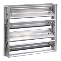
1. On the roof surface,
cut an appropriate
sized hole and follow
manufacturer’s
instructions on curb
installation. Caulk and
flash the curb to ensure
a water tight seal.
2. If unit is equipped with
a backdraft damper, it
should be installed now.
3. Remove motor cover.
Access to the motor
compartment is
accomplished by
removing the screws as shown in Figure 3, page 2.
4a. On belt drive fans, use the lifting lugs on the drive
frame or bearing plate to lift and place the unit on
top of roof curb. Refer to Figure 2, page 2.
4b. On direct drive fans, lift and place the unit on
top of roof curb using hooks under the horizontal
supports. Refer to Figure 1, page 2.
5. Secure fan to curb using a minimum of eight lag
screws, metal screws or other suitable fasteners.
Shims may be required depending upon curb
installation and roofing material.
6. Verify power line wiring is de-energized before
connecting fan motor to power source.
7. For commercial kitchen and UL Listed emergency
smoke control applications, the electrical supply
must enter the motor compartment through
the breather tube. For other non-flammable
applications, the electrical supply can be routed
through the conduit chase between the curb cap
and the bottom of the motor compartment.
8. Connect power supply wiring to the motor as
indicated on the motor nameplate or terminal box
cover. Check the power source for compatibility
with the requirements of your equipment.
9. Check fan wheel for free rotation, recenter if
necessary. Check setscrew(s) for tightness.
10. Check all fasteners for tightness.
11. Mount and wire safety disconnect switch under
motor cover. Wire control switches at ground level,
refer to Figure 6.
12. Replace motor cover.
Figure 5 - Roof Curb Installation
Dimensional Data
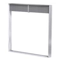
Figure 6 - Typical Wiring Diagram
MOTOR
L1
115/208-230/60/1
208-230/460/60/3
MOTOR
J-BOX
J-BOX
SUPPLY VOLTAGE
SUPPLY VOLTAGE
L2
L1
L2
L3
Belt Drive
Model Size Curb Cap
Shaft
Bearings
Damper
Roof/Wall
Opening
Wall
Opening
with a curb
*Approx.
Weight
099, 101, 101HP,
121, 131
19 (483)
3
⁄4 (19) 12 (305) 14
1
⁄2 (368) 19 (483) 66 (30)
141, 141HP, 161,
161HP
22 (559)
3
⁄4 (19) 16 (406) 18
1
⁄2 (470) 22 (559) 87 (39)
161XP 22 (559) 1 (25) 16 (406) 18
1
⁄2 (470) 22 (559) 87 (39)
180 30 (762)
3
⁄4 (19) 18 (457) 20
1
⁄2 (521) 30 (762) 126 (57)
180HP 30 (762) 1 (25) 18 (457) 20
1
⁄2 (521) 30 (762) 126 (57)
200 30 (762)
3
⁄4 (19) 18 (457) 20
1
⁄2 (521) 30 (762) 142 (64)
200HP 30 (762) 1 (25) 18 (457) 20
1
⁄2 (521) 30 (762) 142 (64)
220, 220HP, 240,
240HP, 240 XP
34 (864) 1 (25) 24 (610) 26
1
⁄2 (673) 34 (864) 175 (79)
300, 300HP,
300XP
40 (1016) 1 (25) 30 (762) 32½ (826) 40 (1016) 313 (142)
360, 360HP,
360XP
46 (1168) 1
1
⁄4 (32) 36 (914) 38
1
⁄2 (978) N/A 440 (200)
420 52 (1321) 1
1
⁄4 (32) 42 (1067) 44
1
⁄2 (1130) N/A 578 (262)
480 58 (1473) 1
1
⁄2 (38) 48 (1219) 50
1
⁄2 (1283) N/A 675 (306)
• All dimensions are in inches (millimeters). *Approximate weight shown in
lbs. (kg.) is the largest cataloged open drip proof motor.
• “Curb Cap” is the inside dimension of the curb cap
• The roof curb should be 1½ in. (38 mm) less than the curb cap to allow for
roofing and flashing.
• Roof/wall opening is a square dimension.