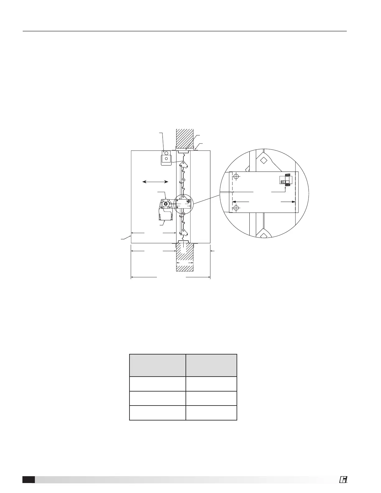
Inserting Damper into Wall/Floor Openings
Insert the sleeved damper assembly into the prepared opening. Refer to label on outside of sleeve for the
recommended location of the damper in the wall or floor (see Dimension A and Detail 1, Figure 8).
Special attention must be paid to ensure the following:
1) The C
L
(centerline) of the damper frame remains within the plane of the wall or floor
2) Attachments made through the retaining angle do not penetrate the ‘No Screw’ area designated on the
damper sleeve.
3) The sleeve does not extend more than 16 in. (406mm) beyond the wall or floor on the actuator side of the
damper and 6 in. (152mm) on the side opposite the actuator. The sleeve may also extend up to 16 in. (406mm)
beyond the wall or floor if the damper has a factory supplied access door.
Optional blade indicator
and/or electric link.
LINE OF WALL
DO NOT INSTALL SCREWS
BETWEEN THESE LINES
AROUND ENTIRE DAMPER
Clearance for expansion
(1/4 in. min., 1 1/2 in. max.)
Retaining Angles
(see Section 4)
Line of Wall
Airflow
Detail 1
DO NOT INSTALL SCREWS
BETWEEN THESE LINES
AROUND ENTIRE DAMPER
Access door required on
jackshaft side of damper.
Refer to the latest edition
of NFPA 90A.
Jackshaft
Actuator
Damper
Sleeve
Sleeve Length (L)
6 in. max.
16 in. max.
‘A’ Dim.
(Distance from
end of sleeve to
face of damper)
458549
T
w
C
L
Figure 8: Properly Installed Combination fire smoke damper
Most fire and combination fire smoke dampers come with factory supplied sleeves. For field supplied sleeves, see
the Field Supplied Sleeves supplement at www.greenheck.com. The following are recommended sleeve lengths for
various wall thicknesses:
Wall Thickness
Dimension (T
W
)
Recommended
Sleeve Length
Dimension (L)
4 - 6 in.
(102mm - 152mm)
16 in.
(406mm)
7 - 10 in.
(178mm - 254mm)
21 in.
(533mm)
11 - 13 in.
(279mm - 330mm)
24 in.
(610mm)
Multi-Blade Fire and Combination Fire Smoke Dampers6