1
Programming Sure-Aire™
®
®
Document 478758
Programming Sure-Aire™
Density Corrections
Air density, , is affected by elevation and temperature. The Greenheck Sure-Aire Differential Pressure Controllers
allow the user to input the elevation for the application. This elevation input automatically updates the density
used for the flow calculation.
The Remote Temperature Sensor will adjust the air density value in the controller based on the sensor
measurement when Temperature Compensation is set to ‘Yes’. This density compensation will affect the flow rate
displayed on the controller. If Temperature Compensation is set to ‘No’, the air density value will be a function of
standard air (70°F/21°C).
The density being used by the Sure-Aire controller can be viewed on the main menu by scrolling up or down
through the settings.
Greenheck Part Number
Controller ∆P Range
(inches W.C.)
P
max
(inches W.C.)
100-240 VAC 24 VAC / VDC
384799 384986 0-8.30 8.30
384800 384987 0-22.14 22.14
384801 384988 0-41.52 41.52
384802 384989 0-83.04 83.04
384803 384990 0-138.40 138.40
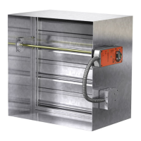
Programming Sure-Aire™
Greenheck’s Sure-Aire™ Differential
Pressure Controller provides either a
2-10 Vdc or 4-20 mA electrical output
signal. The output signal is linearly
proportional to the pressure range of
differential pressure controller. The
ranges for Greenheck’s Sure-Aire
controllers are listed in the table.
Calculating Flow from Differential Pressure
The volumetric flow through the fan (cfm) can be calculated from the equation:
where K is the K-factor for the specific fan model and size, ∆P is the measured differential pressure across the
inlet cone (inches W.C.), and is the air density (lb/ft
3
). K-factors for Greenheck models are found on the back of
this document.
CFM = K
∆P
Calculating Flow from Voltage Signal
If using a 2-10 Vdc output signal from a differential pressure controller, this equation can be used to calculate the
flow:
where V is the output voltage of a 2-10 Vdc transmitter and P
max
is the maximum pressure range of the controller
being used (inches W.C.).
CFM = K
(V - 2) P
max
8
Calculating Flow from Current Signal
If using a 4-20 mA output signal from a differential pressure controller, this equation can be used to calculate the
flow:
where mA is the output current of a 4-20 mA transmitter and P
max
is the maximum pressure range of the
controller being used (inches W.C.).
CFM = K
(mA - 4) P
max
16