High Volume, Low Speed Ceiling Fans18
®
Fire Alarm Relay Installation
The following instructions apply to fans that were
supplied with plug-and-play factory wiring.
DANGER
Always disconnect, lock and tag power source before
installing or servicing. Failure to disconnect power
source can result in fire, shock or serious injury.
DANGER
Pour écarter les risques d’incendie, de choc électrique
ou de blessure grave, veiller à toujours débrancher,
verrouiller et étiqueter la source de courant avant
l’installation ou l’entretien.
NOTE: The following instructions are only applicable
to buildings that are equipped with a fire suppression
system. If the building does not contain a fire
suppression system, leave the crimp connector on
the fire alarm landing point (located at the top of the
downtube) and continue with the rest of the installation.
IMPORTANT: The fire alarm relay should only be
installed by qualified personnel who are familiar with
the operation of building fire suppression systems. It is
the sole responsibility of the installer to ensure correct
operation of the fire alarm relay in the event of a fire
emergency in the building.
Included Component:
• Low Voltage (24VDC/VAC or 115VAC), Normally
Closed Relay (1)
Hardware/Tools Needed (Not Included):
• Standard Screwdriver
• Cable Cutters
• Wire Strippers
1. If the building is equipped with a fire suppression
system, remove the crimp connector from the fire
alarm emergency stop landing point located at the
top of the downtube by snipping the wires directly
below the crimp connector.
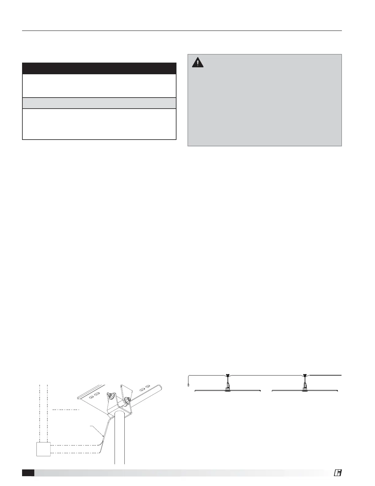
2. Strip the loose wires and wire the supplied
normally-closed relay to the fire alarm emergency
stop landing point and the building’s fire
suppression system using the wiring diagram
shown.
TO FIRE SUPPRESSION SYSTEM
TO LANDING POINT AT FAN
N.C.
RELAY
PRE-WIRED FIRE
ALARM LANDING POINT
WIRING BY OTHERS
Communication Wiring & Fan Control
Installation
IMPORTANT: DS fans must be installed with the
supplied CAT-5e communication cable or
shielded CAT-5e (by others) that complies with
the following specifications. Cable must be
twisted pair, shielded 26 ga. CAT-5e cable with a
drain wire and must be compliant with ISO
11801. Cable must use shielded RJ45
connectors with a soldered drain and wiring
configuration must follow EIA/TIA T568B wiring
pinout. Individual CAT-5e cable lengths must not
exceed 200 ft. in order to prevent network
communication issues.
With Pre-Built CAT-5e Cable
Included Component:
• 100 – 200 ft. CAT-5e Control Cable (1)
Hardware/Tools Needed (Not Included):
• Fan Control (1, optional)
1. Plug one end of the CAT-5e control cable into
the 2-way RJ45 splitter located at the top of the
downtube. The cable can be plugged into any
open receptacle on the splitter.
2. Identify the desired location for installation of the
fan control and run the remainder of the CAT-5e
control cable to this location.
3. Secure the CAT-5e control cable to the building
structure to ensure it does not interfere with fan
performance. To prevent communication issues, do
not coil excess control cable or route control cable
with power wiring.
4. If provided, mount the optional fan control in the
desired location and plug the CAT-5e cable into
the RJ45 port on the control. Otherwise, install
and wire the control source according to the
manufacturer’s instructions.
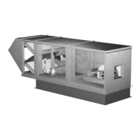
5. If one control source will be used to operate
multiple fans, the fans can be daisy-chained
together to create a network using the following
instructions.
FAN 1
CONTROL
FAN 2
a. Wire the first fan in the chain to the control
source using steps 1-4 above.
b. Plug an additional CAT-5e control cable into the
2-way RJ45 splitter located at the top of the
downtube on the first fan. Connect the other
end of this CAT-5e cable into the 2-way splitter
on the next fan.
Wiring and Electrical – Factory Wiring Installation