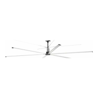
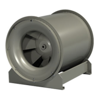
High Volume, Low Speed Ceiling Fans 23
®
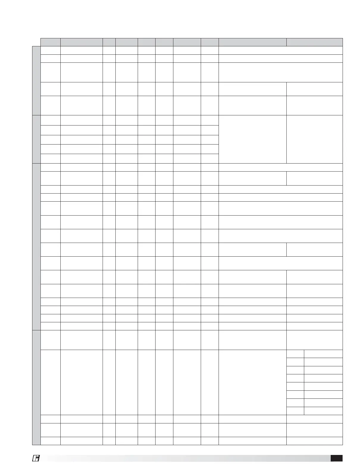
Register Name R/W Retentive Signed Format Range Default Description Detail
Control
1 Run Command R/W x 0,1,2 0=Stop=clear Fault(s); 1=Forward; 2=Reverse; 99=Reset
2 Speed Reference R/W xxx 1...100 Percentage of full speed/torque
3 Operational Status R x 0…6
1=Comm CRC errors, 2=Drive Faulted, 3=Motor temp
warning, 4=IGBT temp warning, 5=Drive Inhibited (Fire
Input), 6=Wind Shut Down active
4 Light Control R/W xxx 0..100 0
J5 0-10V Output for Optional
Light Control (%)
Resets to 0 after power
cycle
5
External
Temperature
R xxxxx -400..1100 External Temp (°C) (0.1 unit)
Based off an external
10K @ 25C NTC
thermistor
Fault
6 Last Fault Code R R xxx
Integer code representing
fault history
At each fault occurance,
values are shifted to next
register and the current
fault is displayed in Last
Fault Code. Values are
retained after power
cycle.
7 Second Last Fault R R xxx
8 Third Last Fault R R xxx
9 Fourth Last Fault R R xxx
10 Fifth Last Fault R R xxx
Diagnostics
11 Firmware Version R R xxxxx 1-500 Incremental Version Count
12 Operating Hours R R xxxxx 0-65535
Operating hours (driving
motor)
MAX 65535
13 Motor RPM R S xxx -300…300 Motor RPM (0.1 rpm)
14 Voltage, DC Bus R xxx 0…1000 Bus Voltage (Volts) (1 units)
15
Voltage, Output
RMS
R xxx 0…1000 RMS Modulated Output Voltage (Volts) (1 units)
16
Current, Motor
RMS
R xx.x 0…150
RMS Motor current (Amps)
(0.1 units)
17
Temperature,
Motor
R S xxx.x -300…1100 Motor Temp (°C) (0.1 units)
18
Temperature,
Transistor
R S xxx.x -400…1250
Transistor Temp (°C) (0.1
units)
Transistor to Heatsink
19
Temperature,
MCU
R S xxx.x -300…1350 MCU Temp (°C) (0.1 units)
20
Thermal Speed
Derate
R xxx 0…100
Speed/Torque derate based
on overtemp (%)
Thermal regulation
(Motor and/or Drive)
21
Communication
Errors
R xxx 0-65535
Number of errors since last
power cycle
0-65535
22 -- Spare -- R 0
23 -- Spare -- R 0
24 -- Spare -- R 0
25 -- Spare -- R 0
Configuration
26
KEEP ALIVE
(WatchDog)
R/W R xxxxx 0-65535 30 Seconds
Any message resets; if a
timeout occurs, fan will
stop (if running)
27
MODBUS Serial
Speed
R/W x 0…9 5
Baud Rate Setting
(SW2: Pin 7 ON)
0 1200 bps
1 2400 bps
2 4800 bps
3 9600 bps
4 19200 bps
5 38400 bps
6 57600 bps
7 115200 bps
28 Motor Type R/W 0..2 0 13,70,170 0=13; 1 = 70; 2=170
29
MODBUS Device
ID
R/W R 1-247 2
New Device ID is set after
power cycle
SW2 PIN 8 must be set
(on) for this to take effect
30 -- Spare -- R/W 0
NOTE: Registers 1000-1150 are reserved for internal Diagnostics and Testing.
Modbus Registers
The DS fan’s VFD is configured for Modbus RTU communication as standard. The Modbus register list is for
applications where a building management system or field-supplied control are to be used for fan operation.