Microprocessor Controller for DOAS 15
®
The microprocessor controller will revert to a default main menu loop. This loop includes several screens to view the
operating conditions of the unit. Scroll through the menu screens by using the
buttons.
Unit Status Overview
Unit Status Screen Symbols
Symbol Indicates
Supply air fan status.
Rotation indicates airflow; static blades indicate no airflow.
Cooling
Heating
Dehumidifying
Economizing
Defrost
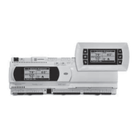
THE INITIAL MENU SCREEN DISPLAYS THE JOB NAME, UNIT TAG, UNIT STATUS, OUTSIDE
AIR CONDITIONS, SPACE CONDITIONS AND SETPOINTS.
Possible modes include:
• Off/Standby
• Unoccupied Start
• Dampers Open
• Fan Start Delay
• Fans Starting
• Startup Delay
• System On
• Soft Shutdown
• System Disabled
• Remote Off
• Shutdown Alarm
• Fans Only
• Economizing
• Cooling
• Dehumidifying
• Heating
• HGRH Purging
• Defrost Active
• Overrides Active
• Expansion Offline
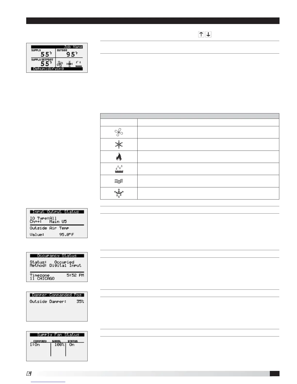
INPUT OUTPUT STATUS
Displays real time conditions from sensors located in the unit and building space
if equipped with space mounted sensors. Controller output conditions can also
be viewed from this screen. To view the desired input/output point, the user must
select the desired channel. Reference the Controller Overview section in this IOM
for individual point locations.
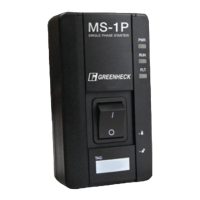
OCCUPANCY STATUS
Displays current status of occupancy and the configured occupancy control
method and time zone.
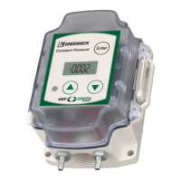
DAMPER COMMANDED POS
This screen appears if equipped with modulating outdoor air and recirculated air
dampers. Displays current position of the outdoor air damper. Recirculating air
damper position is the inverse of outside damper position.
SUPPLY FAN STATUS
This screen displays the fan enable command, fan proving status, and the supply
fan ramp being sent from the controller to the VFD. The minimum and maximum
speeds are set in the VFD (Reference unit Installation and Operation Manual for
VFD programming). The controller can modulate the fan between the min and
max speeds via an analog output.