Microprocessor Controller for DOAS 25
®
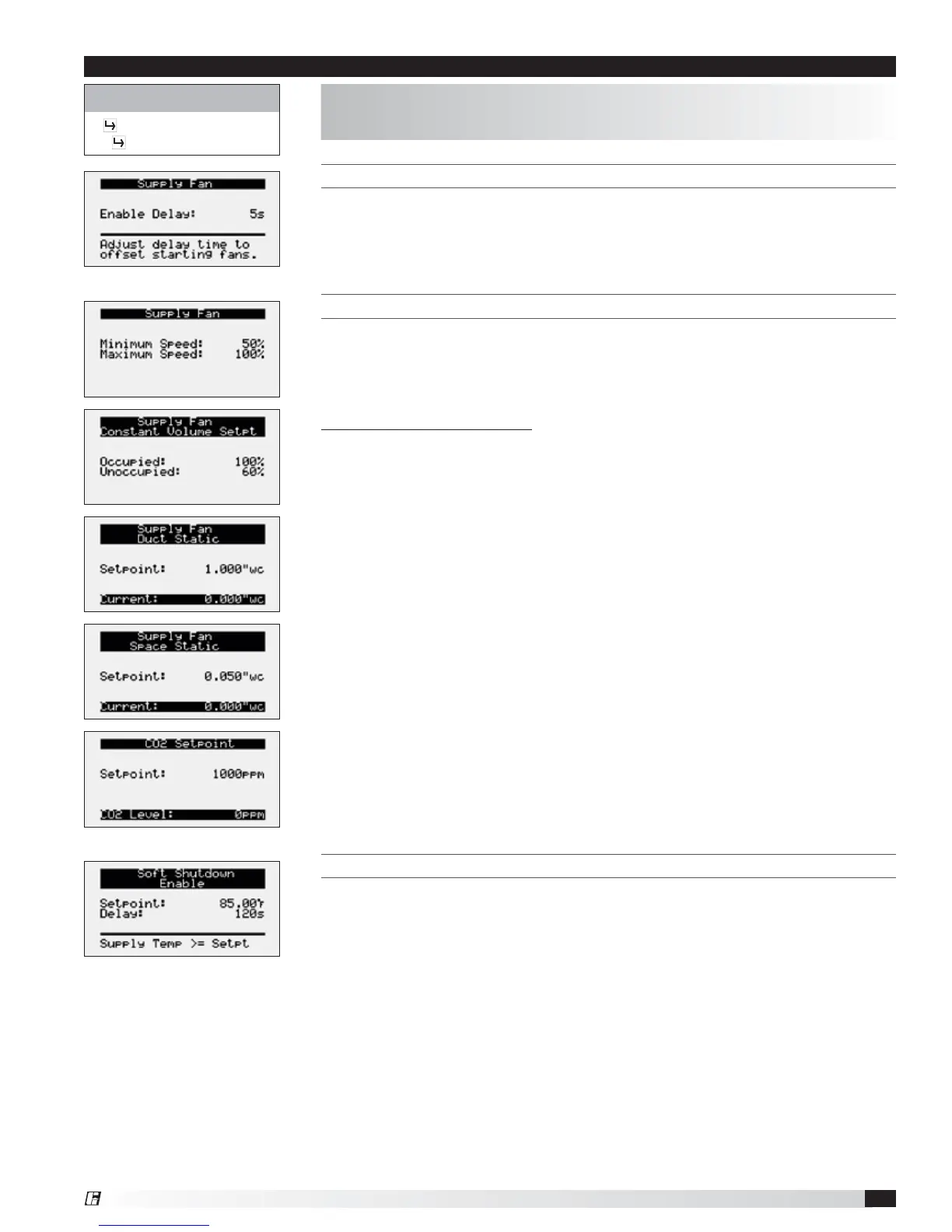
THIS SCREEN DISPLAYS THE SUPPLY FAN DELAY.
The supply fan delay will begin once the damper sequence is complete. This delay
can be used to offset starting times between the supply fan and exhaust fan.
THIS SCREEN DISPLAYS MINIMUM AND MAXIMUM SUPPLY FAN SPEED PERCENTAGES.
The speed set point is the proportional percentage of the analog output from the
controller to the VFD.
50% Speed = Min speed
100% Speed = Max speed
Possible Setpoint Sources:
Local – The fan speed will be constant; set from screen (e.g. 100%).
BMS – The BMS can directly control the fan speed (requires BMS communication
option).
Duct Pressure – Fan speed is determined by duct pressure control loop.
Space Pressure – Fan speed is determined by building pressure control loop.
CO
2
– Fan speed is determined by CO
2
control loop.
Single Zone VAV - The supply fan is modulated in addition to the supply air
temperature to satisfy the room temperature set point. A room temperature
sensor is required.
2-Speed (High Speed Set Point) - Supply fan speed is reset to maximum speed
when a contact closure is made. (Max Ventilation Mode).
THIS SCREEN DISPLAYS SOFT SHUTDOWN ENABLE CONDITIONS.
During a soft shutdown the following will occur:
• Tempering outputs immediately revert back to their off value; while
• Dampers remain open and fans continue to run; until
- The supply air temperature falls below the soft shutdown enable setpoint
minus 5.0ºF; or
- The soft shutdown delay timer has expired.
Control Variables
Fan Control
Supply Fan Control
The Supply Fan Control menu allows the user to adjust exhaust control
setpoints
Menu